1. Introduction
This manual provides comprehensive instructions for the installation, operation, and maintenance of the AXIS F9111 Main Unit. The AXIS F9111 is a crucial component of the F-Series, designed to integrate with F21 and F7 sensor units to provide advanced surveillance capabilities. It serves as the central processing unit for connected camera sensors, handling video streams, audio, and I/O signals.
2. Product Features
- Model Number: 01990-001
- Compact design with a weight of approximately 2.0 kg (4 pounds).
- Designed for integration within the AXIS F-Series surveillance system.
3. Package Contents
Please verify the contents of your package against the packing list provided with your AXIS F9111 Main Unit. Typically, the package includes:
- AXIS F9111 Main Unit
- Installation Guide
- Power Adapter (if not using Power over Ethernet)
- Mounting Accessories (if applicable)
Note: Actual contents may vary. Refer to your specific product packaging for details.
4. Setup and Installation
Follow these steps to set up your AXIS F9111 Main Unit. Ensure all connections are secure before powering on the device.
4.1. Overview of Ports and Indicators
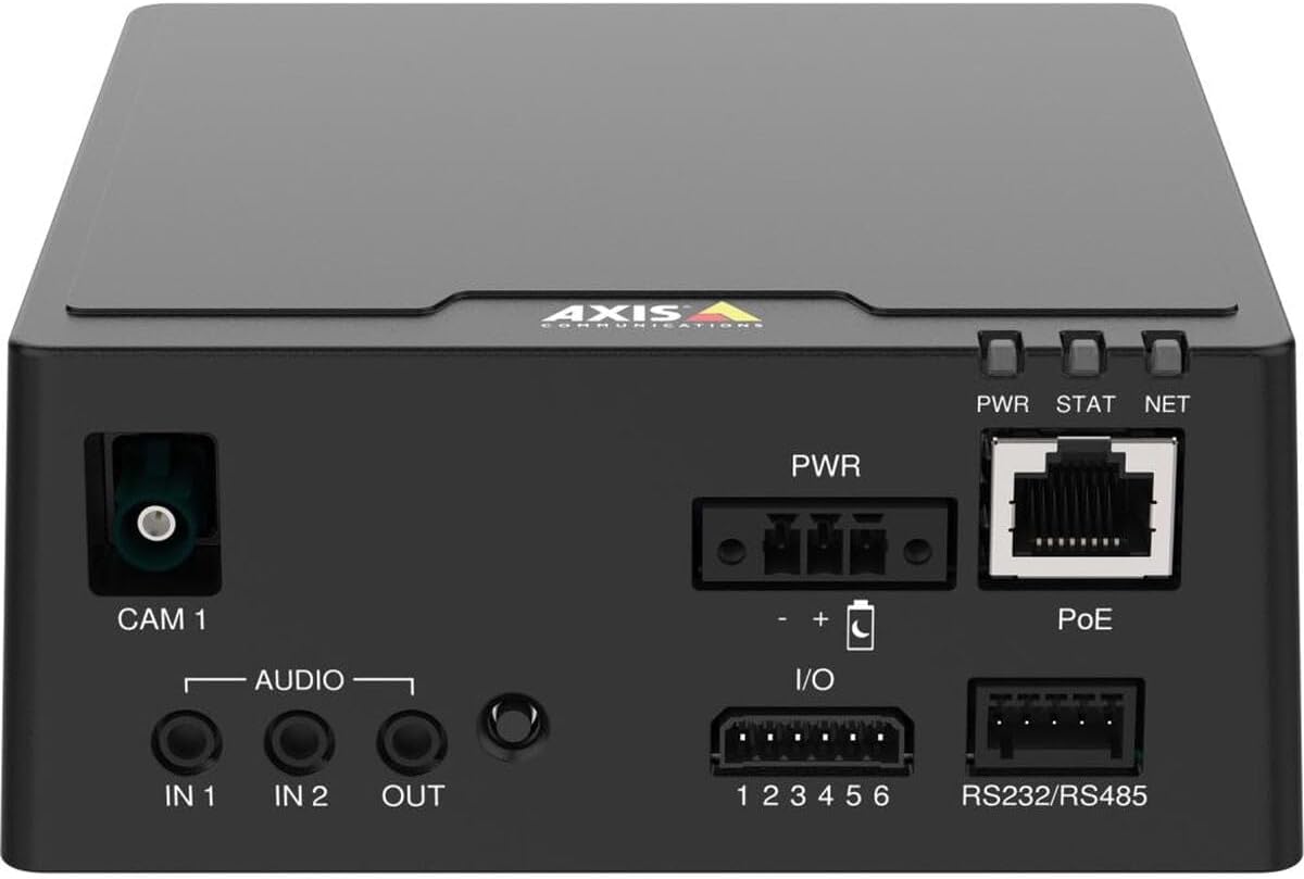
Figure 1: Top-down view of the AXIS F9111 Main Unit, highlighting the various connection ports and status indicators. From left to right, it shows the CAM 1 input, Audio IN/OUT, PWR input, I/O terminals, PoE Ethernet port, RS232/RS485 terminals, and PWR, STAT, NET LED indicators.
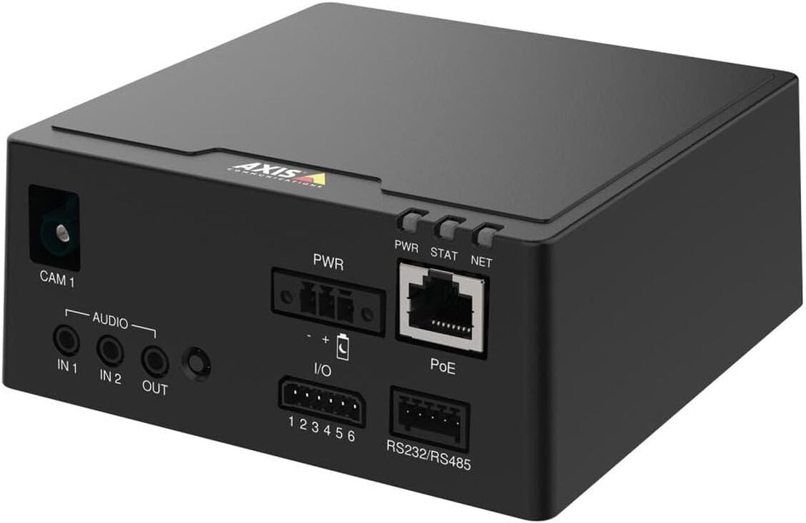
Figure 2: Angled perspective of the AXIS F9111 Main Unit, providing a clearer view of the front panel connections including CAM 1, Audio IN/OUT, PWR, I/O, PoE, and RS232/RS485 ports, along with the status LEDs.

Figure 3: A different angled view of the AXIS F9111 Main Unit, further illustrating the layout of the various input/output ports and power/network connections for comprehensive system integration.
4.2. Connection Steps
- Connect Sensor Unit: Connect an AXIS F-Series sensor unit (e.g., F21, F7) to the CAM 1 port. Ensure the connection is firm.
- Power Connection:
- Power over Ethernet (PoE): Connect an Ethernet cable from a PoE-enabled switch or injector to the PoE port on the main unit. This will provide both power and network connectivity.
- External Power: If PoE is not used, connect a compatible power adapter to the PWR input.
- Network Connection: If not using PoE, connect an Ethernet cable from your network to the PoE port. This port functions as a standard Ethernet port when not receiving PoE.
- Audio Connections: If required, connect external audio devices to the AUDIO IN 1, IN 2 (inputs) and OUT (output) ports.
- I/O Connections: For external device control or alarm integration, connect to the I/O (1-6) terminals. Refer to the detailed wiring diagram in the full technical manual for specific configurations.
- Serial Communication: For serial data communication, connect devices to the RS232/RS485 terminals.
- Power On: Once all connections are made, power on the unit. Observe the PWR, STAT, NET LED indicators for status.
5. Operating the AXIS F9111 Main Unit
The AXIS F9111 Main Unit operates as the central hub for your connected AXIS F-Series sensor units. Once powered on and connected to the network, it can be accessed and configured via a web browser or AXIS Camera Station software.
5.1. Initial Access and Configuration
- Discover Device: Use AXIS IP Utility or AXIS Device Manager to discover the unit on your network.
- Access Web Interface: Open a web browser and enter the IP address of the unit. Log in using the default credentials (or those you have set).
- Configure Settings: Within the web interface, you can configure video streams, audio settings, I/O events, network parameters, and user access.
5.2. LED Indicators
- PWR (Power): Indicates power status. Typically solid green when powered on.
- STAT (Status): Indicates operational status. Blinking patterns may indicate different states (e.g., booting, error). Refer to the full user manual for detailed status codes.
- NET (Network): Indicates network activity. Blinks when data is being transmitted or received.
6. Maintenance
Regular maintenance ensures optimal performance and longevity of your AXIS F9111 Main Unit.
- Cleaning: Use a soft, dry cloth to clean the exterior of the unit. Do not use harsh chemicals or abrasive materials. Ensure no liquids enter the ports.
- Firmware Updates: Periodically check the Axis Communications website for firmware updates. Keeping the firmware updated ensures you have the latest features, security patches, and bug fixes. Follow the instructions provided with the firmware update package carefully.
- Environmental Conditions: Ensure the unit is operated within its specified temperature and humidity ranges to prevent damage. Avoid exposing the unit to direct sunlight, excessive dust, or moisture.
7. Troubleshooting
If you encounter issues with your AXIS F9111 Main Unit, refer to the following common troubleshooting steps:
| Problem | Possible Cause | Solution |
|---|---|---|
| Unit does not power on (PWR LED off) | No power supply; faulty power adapter/PoE; loose connection. | Check power cable connection. Verify power outlet. Ensure PoE switch/injector is active. Try a different power source if available. |
| No network connectivity (NET LED off/no blink) | Ethernet cable disconnected/faulty; incorrect network settings; network issue. | Check Ethernet cable connection. Verify network settings (IP address, subnet mask). Restart network equipment (router/switch). |
| No video from connected sensor unit | Sensor unit not connected properly; faulty sensor unit; software configuration issue. | Ensure sensor unit is firmly connected to CAM 1 port. Check sensor unit's functionality. Verify video stream settings in the unit's web interface. |
| STAT LED blinking rapidly/red | Error state; firmware issue. | Refer to the full Axis Communications user manual for specific STAT LED error codes. Try restarting the unit. Consider a firmware reinstallation if persistent. |
For more detailed troubleshooting or advanced issues, please refer to the official Axis Communications support documentation or contact their technical support.
8. Specifications
| Attribute | Detail |
|---|---|
| Brand | Axis Communications |
| Model Number | 01990-001 |
| Item Weight | 4 pounds (approx. 2.0 kg) |
| Product Dimensions (LxWxH) | 19.69 x 19.69 x 11.02 inches |
| Manufacturer | AXIS - CAMERA |
| ASIN | B0BWNP6NGD |
| Date First Available | March 29, 2023 |
9. Warranty and Support
The AXIS F9111 Main Unit is manufactured by Axis Communications. For warranty information, please refer to the official warranty statement provided with your product or visit the Axis Communications website.
Optional protection plans may be available for purchase, such as a 4-Year Protection Plan or a Complete Protect plan. These plans are separate from the manufacturer's warranty and offer extended coverage.
For technical support, product documentation, and software downloads, please visit the official Axis Communications support portal:
Visit Axis Communications Support
For returns, please adhere to the return policy of your retailer, which typically allows for returns within 30 days of purchase.


