1. Introduction
This manual provides detailed instructions for the installation, operation, and maintenance of the RackChoice 4U Rackmount Server Chassis. This chassis is designed for high-performance server applications in data centers and small to medium-sized businesses (SMBs), supporting a variety of motherboard form factors and offering hot-swappable drive bays for efficient storage management.

Figure 1.1: Front view of the RackChoice 4U Rackmount Server Chassis, showcasing the 8 hot-swappable drive bays and front panel controls.
2. Safety Information
Please read and understand all safety instructions before installing or operating the server chassis. Failure to follow these guidelines may result in injury, equipment damage, or voiding of the warranty.
- Electrical Safety: Always disconnect power from the chassis and all connected components before performing any installation or maintenance. Ensure proper grounding.
- Weight: The chassis can be heavy, especially when fully populated with components. Use proper lifting techniques or seek assistance to prevent injury.
- Sharp Edges: Be cautious of sharp edges inside the chassis during installation to avoid cuts.
- Ventilation: Ensure adequate airflow around and within the chassis. Do not block ventilation openings.
- Static Electricity: Use an anti-static wrist strap when handling internal components to prevent electrostatic discharge (ESD) damage.
3. Package Contents
Verify that all items listed below are present in your package. If any items are missing or damaged, please contact RackChoice customer support.
- RackChoice 4U Rackmount Server Chassis
- 28-inch Sliding Rail Kit (1 set)
- MiniSAS (SFF-8643) HDD Backplane (pre-installed)
- 2 x Reversed SFF-8643 Male to 4xSATA 7pin Female Cables
- Accessory Kit (screws, standoffs, cable ties)

Figure 3.1: Chassis with included 28-inch sliding rails and MiniSAS to SATA cables.

Figure 3.2: Included accessory kit containing screws and mounting hardware.
4. Product Features
The RackChoice 4U Rackmount Server Chassis offers robust features for demanding server environments:
- Motherboard Compatibility: Supports EATX, ATX, MicroATX, and Mini-ITX motherboards.
- Drive Bays: 8 x 3.5-inch hot-swappable SATA/SAS drive bays (2.5-inch compatible) and 1 x 3.5-inch fixed drive bay (or 2 x 2.5-inch fixed).
- Cooling System: Three pre-installed 120mm PWM ball bearing fans with options for additional rear cooling. Backplane supports PWM fan for auto speed control.
- Expansion Slots: Eight full-height expansion slots for various add-on cards.
- Power Supply: Supports standard ATX power supply or CRPS redundant PSU.
- Connectivity: MiniSAS (SFF-8643) HDD backplane for efficient drive connectivity.
5. Setup and Installation
5.1 Opening the Chassis
To access the internal components, remove the four screws securing the top lid of the chassis. Carefully lift the lid off.
5.2 Motherboard Installation
- Align the motherboard with the standoffs inside the chassis.
- Secure the motherboard using the appropriate screws from the accessory kit.
5.3 Drive Installation
5.3.1 Hot-Swappable 3.5-inch/2.5-inch Drives
- Gently pull the lever on the desired hot-swap drive tray to release it.
- For 3.5-inch drives, align the drive with the tray and secure it without screws (the tray design typically holds it in place).
- For 2.5-inch drives, you may need an adapter bracket (not included) or follow the specific instructions for 2.5-inch mounting within the 3.5-inch tray.
- Slide the populated tray back into the bay until it clicks securely into place.

Figure 5.1: Illustrates the method for installing a 2.5-inch HDD into a drive tray.
5.3.2 Fixed 3.5-inch/2.5-inch Drives
The chassis includes an internal mounting bracket for one 3.5-inch drive or two 2.5-inch drives.
- Locate the internal mounting bracket (refer to Figure 5.2).
- Secure your 3.5-inch or 2.5-inch drives to this bracket using the provided screws.
- Connect the necessary power and data cables to these drives.

Figure 5.2: Internal mounting bracket for additional 3.5-inch or 2.5-inch drives.
5.4 Power Supply Unit (PSU) Installation
- Slide the ATX or CRPS power supply into its designated bay at the rear of the chassis.
- Secure the PSU with screws from the accessory kit.
- Connect the main power cables to the motherboard and other components.
5.5 Expansion Card Installation
- Remove the appropriate slot cover(s) at the rear of the chassis.
- Insert the expansion card into the corresponding PCIe slot on the motherboard.
- Secure the expansion card with a screw.

Figure 5.3: Rear view of the chassis, highlighting the eight full-height expansion slots.
5.6 Cable Connections
- Connect the two provided SFF-8643 to 4xSATA cables from your motherboard's SAS/SATA controller to the MiniSAS (SFF-8643) ports on the HDD backplane.
- Connect the Peripheral Power Connector (D4) on the backplane to your PSU.
- Connect the front panel cables (power switch, reset switch, USB ports, LEDs) to the corresponding headers on your motherboard. Ensure correct polarity for LEDs.
- Connect the 4-pin PWM fan cables from the backplane to your motherboard's fan headers for automatic speed control, if desired.

Figure 5.4: Detailed diagram of the MiniSAS HDD backplane, showing MiniSAS (SFF-8643) ports, Peripheral Power Connector (D4), PWM Control Jumper, and PWM Fan 4PIN socket.
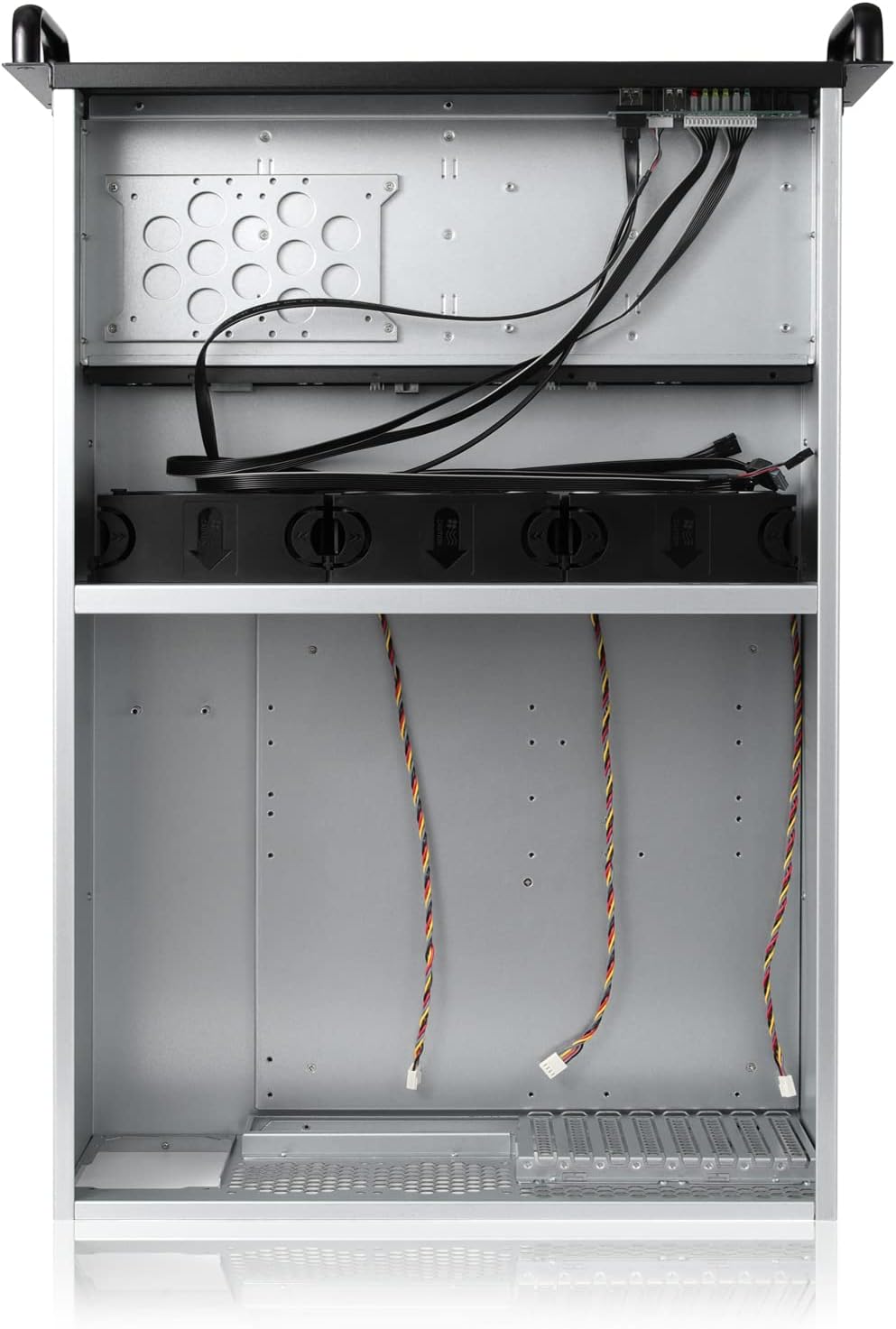
Figure 5.5: Internal view of the chassis, illustrating cable routing and component placement.
5.7 Rack Installation (with 28-inch Sliding Rail Kit)
The included 28-inch sliding rail kit simplifies chassis installation into a standard server rack.
- Install Inner Rails: Attach the inner rails to the sides of the server chassis using the provided screws.
- Install Outer Rails: Mount the outer rails onto the server rack posts. Ensure they are level and securely fastened.
- Slide Chassis into Rack: Carefully align the inner rails (attached to the chassis) with the outer rails (attached to the rack). Slide the chassis into the rack until it locks into place.
6. Operating Instructions
6.1 Powering On/Off
Press the power button on the front panel to turn the server on. To turn off, perform a graceful shutdown through your operating system, then press the power button. For a forced shutdown, press and hold the power button for several seconds.
6.2 Hot-Swapping Drives
The 8-bay hot-swappable design allows for drive replacement without powering down the server, provided your operating system and RAID controller support hot-swap functionality.
- Before removing a drive, ensure it is safely ejected or unmounted from your operating system.
- Gently pull the lever on the drive tray to release it and slide the drive out.
- Insert the new drive into an empty tray or replace an existing one, ensuring it is properly seated.
- Slide the tray back into the bay until it clicks securely. The system should detect the new drive automatically.
7. Maintenance
7.1 Cleaning
Regularly clean the chassis to ensure optimal performance and longevity. Use a soft, dry cloth to wipe exterior surfaces. For internal cleaning, use compressed air to remove dust from fans and components. Always power down and disconnect the server before cleaning internal parts.
7.2 Fan Replacement
The chassis features hot-swappable fans. If a fan fails or becomes excessively noisy, it can be replaced. Ensure the replacement fan matches the specifications of the original (120mm PWM ball bearing fan) for optimal cooling and compatibility with the backplane's auto speed control.
8. Troubleshooting
- Loud Fan Noise: The pre-installed fans are high-performance. If noise is a concern, ensure the PWM fan control is enabled in your motherboard's BIOS/UEFI settings. Consider replacing with quieter, compatible PWM fans if necessary.
- Drives Not Detected: Verify all MiniSAS to SATA cables are securely connected to both the backplane and your motherboard/controller. Ensure the backplane's power connector is properly attached to the PSU.
- Chassis Does Not Fit Rack: The chassis has a depth of 26.77 inches (677mm) without handles, and approximately 28 inches (710mm) with handles/rails. Ensure your rack has sufficient depth. Standard rack openings are 19 inches wide; confirm your rack meets this specification.
- SATA to MiniSAS Cable Length: The included cables are designed for standard configurations. If your motherboard's SAS/SATA controller is located far from the backplane, you may need to acquire longer SFF-8643 cables.
- Front Panel Pins: Ensure front panel power, reset, and LED cables are connected to the correct motherboard headers with the correct polarity.
9. Specifications
| Feature | Specification |
|---|---|
| Model | 4U Rackmount Server Chassis |
| Dimensions (D x W x H) | 26.77" x 19" x 7" (677mm x 482mm x 178mm) |
| Item Weight | 15.3 pounds (6.94 kg) |
| Material | Alloy Steel |
| Drive Bays | 8 x 3.5" Hot-Swap SATA/SAS (2.5" compatible), 1 x 3.5" Fixed (or 2 x 2.5" Fixed) |
| Motherboard Support | EATX, ATX, MicroATX, Mini-ITX |
| Expansion Slots | 8 x Full-Height |
| Cooling | 3 x 120mm PWM Ball Bearing Fans (front), optional rear cooling |
| Power Supply Support | Standard ATX PSU or CRPS Redundant PSU |
| Backplane | MiniSAS (SFF-8643) HDD Backplane |

Figure 9.1: Side view of the chassis with key dimensions, including depth (26.7 inches / 677mm without handles).
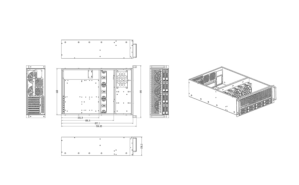
Figure 9.2: Technical drawing providing comprehensive dimensions for the chassis.
10. Warranty and Support
RackChoice products are covered by a limited warranty. For specific warranty terms and conditions, please refer to the warranty card included with your product or visit the official RackChoice website. For technical support, troubleshooting assistance, or to inquire about replacement parts, please contact RackChoice customer service through the contact information provided on our website or your purchase documentation.


