1. Introduction
This manual provides essential information for the safe and effective operation of the H HOLDPEAK T6-VC60B Digital Insulation Resistance Tester. Please read this manual thoroughly before using the device and retain it for future reference.
The T6-VC60B is a versatile digital megohmmeter designed for measuring insulation resistance, AC/DC voltage, and circuit resistance. It features multiple test voltages (250V, 500V, 1000V) for insulation resistance, a wide measurement range up to 2GΩ, and includes features like data hold, backlight, and high voltage/short circuit alarms.
2. Safety Information
WARNING: Electrical testing can be hazardous. Always follow safety precautions to prevent electric shock or personal injury.
- Always ensure the device is in good working condition before use. Do not use if damaged.
- Do not operate the tester in wet environments or with wet hands.
- Verify the test leads are properly connected and undamaged.
- Always disconnect power to the circuit under test before making connections for resistance or insulation measurements.
- Be aware of the high voltage output during insulation resistance tests. The "E" output jack will output high voltage.
- Observe all local and national safety codes.
- Do not attempt to repair or modify the device. Refer servicing to qualified personnel.
- Replace batteries promptly when the low battery indicator appears to ensure accurate readings.
3. Product Overview
The H HOLDPEAK T6-VC60B is designed for reliable and accurate electrical measurements. Key components and features are outlined below.

Figure 1: Front view of the T6-VC60B Insulation Resistance Tester with key components labeled.
- 1. LCD display: Shows measurement readings and indicators.
- 2. Shoulder strap locker: Point for attaching the shoulder strap.
- 3. Terminal of DC 9V DC adapter: Input for external 9V DC power supply (adapter not included).
- 4. E: Insulation resistance input jack: High voltage output terminal for insulation resistance measurements.
- 5. G: Protection jack: Ground terminal for insulation resistance measurements.
- 6. V/Ω: Voltage measurement, resistance measurement (<2KΩ) and continuity measurement positive input jack: Positive input for voltage, resistance, and continuity.
- 7. L: Connecting the measured circuit jack: Common/negative input for all measurements.
- 8. Power switch / function knob: Rotary switch to turn the device ON/OFF and select measurement functions (250V, 500V, 1000V, ACV, DCV, Resistance).
- 9. High voltage indicator (LED): Lights up when high voltage is present during insulation tests.
- 10. Test button: Initiates insulation resistance measurement.
- 11. LCD backlight ON/OFF key: Toggles the display backlight.
- 12. DATA HOLD key: Freezes the current reading on the display.

Figure 2: Key design features including battery compartment, external power socket, shoulder strap, and backlit LCD.
- Battery Snap Design: Prevents batteries from falling or sliding out.
- External 9V Power Supply Socket: Allows for long-term power supply using an external 9V DC adapter (not included).
- Shoulder Strap Design: Provides hands-free operation and prevents accidental drops. The strap is detachable.
- Backlit LCD Display: Enhances readability in dim-light conditions.

Figure 3: The shoulder strap and robust protective cover for enhanced portability and durability.
The sturdy protective cover safeguards the operating panel, and the non-slip design on the sides ensures a secure grip.
4. Setup
4.1 Battery Installation
The T6-VC60B is powered by six 1.5V AA batteries (included).
- Locate the battery compartment on the back of the device.
- Open the battery compartment cover.
- Insert six 1.5V AA batteries, ensuring correct polarity (+/-). The battery snap design helps secure them.
- Close the battery compartment cover securely.
Alternatively, the device can be powered by an external 9V DC power cord (not included) connected to the DC 9V adapter terminal (3).
4.2 Connecting Test Leads
Always ensure test leads are in good condition before connecting them.
- For voltage, resistance, and continuity measurements, connect the red test lead to the V/Ω jack (6) and the black test lead to the L jack (7).
- For insulation resistance measurements, connect the red test lead to the E jack (4) and the black test lead to the L jack (7). If using the guard terminal, connect a third lead to the G jack (5).
5. Operating Instructions
5.1 Powering On/Off and Function Selection
To power on the device, rotate the Power switch / function knob (8) from the "OFF" position to the desired measurement function (e.g., 250V, 500V, 1000V, ACV, DCV, Resistance). To power off, rotate the knob back to "OFF".
5.2 Insulation Resistance Measurement (MΩ)
This function measures insulation resistance from 1MΩ to 2000MΩ with test voltages of 250V, 500V, or 1000V.

Figure 4: Setup for Insulation Resistance Measurement.
- Ensure the circuit under test is de-energized and safely discharged.
- Connect the red test lead to the E jack (4) and the black test lead to the L jack (7).
- Rotate the function knob (8) to the desired insulation test voltage (250V, 500V, or 1000V).
- Connect the test probes to the component or circuit to be measured.
- Press and hold the Test button (10). The High voltage indicator (LED) (9) will light up, and a high voltage symbol will appear on the LCD. A "tick tick" sound indicates high voltage output.
- Read the insulation resistance value on the LCD display (1).
- Release the Test button (10) to stop the test and discharge the circuit.
CAUTION: High voltage is present at the "E" output jack during insulation tests. Handle with extreme care to avoid electric shock.
5.3 AC/DC Voltage Measurement (V)
Measures AC Voltage from 1V to 750V (50Hz to 200Hz) and DC Voltage from 1V to 1000V.
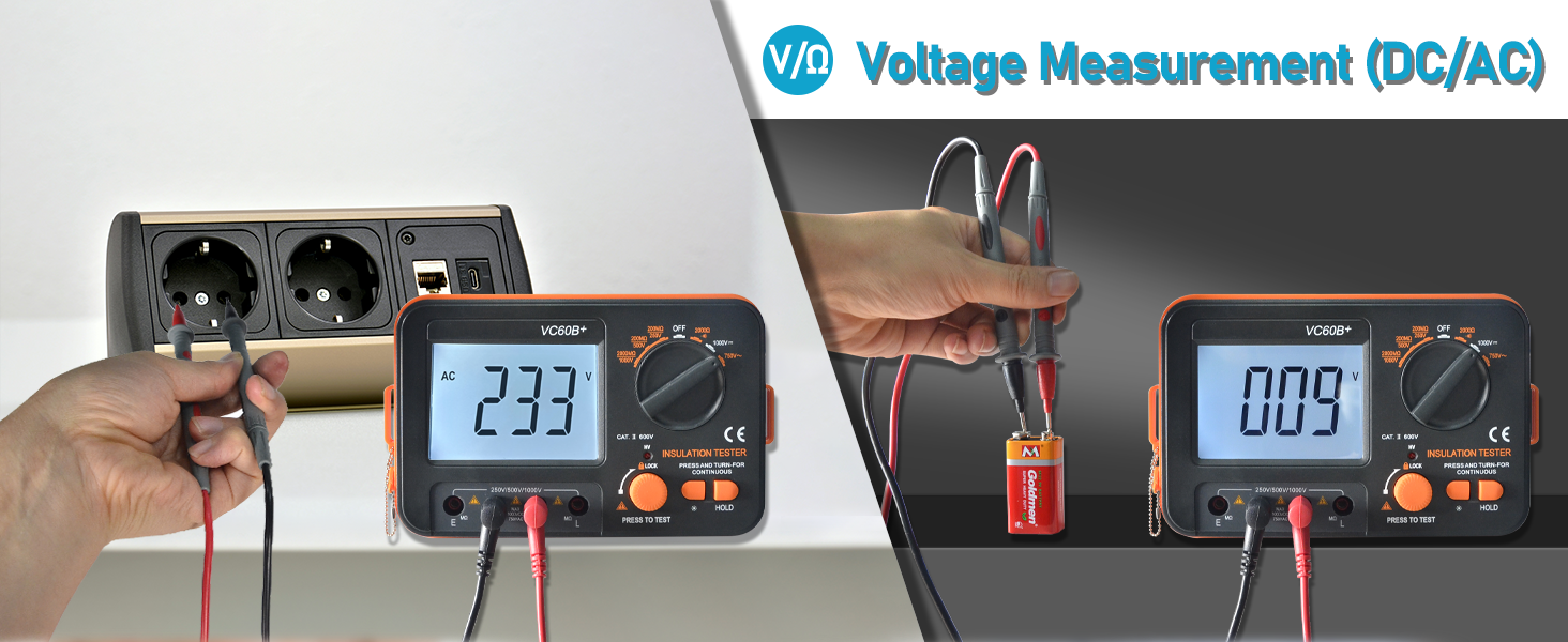
Figure 5: Setup for AC/DC Voltage Measurement.
- Connect the red test lead to the V/Ω jack (6) and the black test lead to the L jack (7).
- Rotate the function knob (8) to the "ACV" or "DCV" position.
- Connect the test probes across the circuit or component where voltage is to be measured.
- Read the voltage value on the LCD display (1).
5.4 Resistance Measurement (Ω) and Continuity
Measures resistance from 0 to 2 KΩ. Also features a continuity buzzer.

Figure 6: Setup for Resistance and Continuity Measurement.
- Ensure the circuit under test is de-energized.
- Connect the red test lead to the V/Ω jack (6) and the black test lead to the L jack (7).
- Rotate the function knob (8) to the "Resistance" position.
- Connect the test probes across the component to be measured.
- Read the resistance value on the LCD display (1). For continuity, the buzzer will sound if resistance is low.
5.5 Data Hold Function
Press the DATA HOLD key (12) to freeze the current reading on the LCD display. Press it again to release the hold function and resume live readings.
5.6 Backlight
Press the LCD backlight ON/OFF key (11) to turn the display backlight on or off, improving visibility in low-light conditions.
5.7 Alarms and Indicators

Figure 7: High-Voltage Audible and Visual Alarm in operation.
- High Voltage Indicator: When the test switch is pressed for insulation resistance, the red warning light (9) will illuminate, a high voltage display symbol will appear on the screen, and the buzzer will emit a "tick tick" sound, indicating high voltage output.
- Short Circuit Buzzer Alarm: If the measured insulation resistance is less than 5% of the range or a short circuit is detected, the buzzer will emit a continuous warning sound. This feature includes automatic zeroing of resistance short circuits.
- Over Range Indication: The display will indicate "OL" or similar when the measurement exceeds the selected range.
- Low Battery Indication: An icon will appear on the LCD when battery power is low, indicating that batteries should be replaced soon.

Figure 8: Short Circuit Buzzer Alarm indication on the display.
6. Maintenance
6.1 Cleaning
Wipe the device with a damp cloth and mild detergent. Do not use abrasive cleaners or solvents. Ensure the device is dry before storage or use.
6.2 Battery Replacement
When the low battery indicator appears on the display, replace all six 1.5V AA batteries as described in Section 4.1. Remove batteries if the device will not be used for an extended period.
6.3 Storage
Store the device in a cool, dry place, away from direct sunlight and extreme temperatures. Keep the protective cover on when not in use.
7. Troubleshooting
| Problem | Possible Cause | Solution |
|---|---|---|
| Device does not power on. | Dead or incorrectly installed batteries. | Check battery polarity and replace batteries if necessary. Ensure the function knob is not in the "OFF" position. |
| Inaccurate readings. | Low battery power; damaged test leads; incorrect function selected. | Replace batteries. Inspect test leads for damage. Verify the correct measurement function is selected. |
| "OL" displayed on screen. | Measurement exceeds the selected range; open circuit. | Select a higher range if available, or check for an open circuit in the component under test. |
| No high voltage alarm during insulation test. | Test button not pressed; device malfunction. | Ensure the Test button is pressed and held. If the issue persists, discontinue use and seek professional service. |
| Short circuit buzzer alarm sounds unexpectedly. | Actual short circuit; very low resistance. | Verify the circuit under test for actual short circuits or extremely low resistance values. |
8. Specifications
| Parameter | Value |
|---|---|
| Model | T6-VC60B |
| Insulation Resistance Test Voltages | 250V, 500V, 1000V |
| Insulation Resistance Range | 1MΩ to 2000MΩ (2GΩ) |
| Insulation Resistance Accuracy (250V/500V) | 0 ~ 200MΩ ±(4.0%+2) |
| Insulation Resistance Accuracy (1000V) | 0 ~ 2000MΩ ±(4.0%+2) |
| AC Voltage Range | 1V to 750V (Frequency 50Hz to 200Hz) |
| DC Voltage Range | 1V to 1000V |
| Resistance Range | 0 to 2 KΩ |
| Display | 1999 Counts Backlit LCD |
| Power Source | 6 x 1.5V AA batteries (included) or external 9V DC adapter (not included) |
| Item Weight | 1.67 pounds (approx. 0.76 kg) |
| Package Dimensions | 7.99 x 6.77 x 2.8 inches (approx. 20.3 x 17.2 x 7.1 cm) |
| Features | Over range Indication, Data Hold, Low Battery Indication, Backlight LCD, High Voltage Buzzer Alarm, High Voltage Red Light Alarm, Short Circuit Buzzer Alarm. |
9. Applications
The H HOLDPEAK T6-VC60B is suitable for measuring the insulation resistance of various types of electrical equipment and insulation materials. Common applications include:
- Transformers
- Cables
- Switches
- Electric motors
- General electrical appliances
- Repairing cables

Figure 9: Examples of applications for the insulation resistance tester.


