Introduction
This manual provides essential information for the installation, operation, and maintenance of your HD Switch Safety Interlock Switch. This OEM quality replacement switch is designed for use with various Cub Cadet PRO Z 500, 700, and 900 Series lawn and garden zero-turn mowers. Please read this manual thoroughly before installation and operation to ensure proper function and safety.
Safety Information
Always prioritize safety when working with electrical components and machinery. Failure to follow these safety guidelines may result in injury or damage to equipment.
- Disconnect Power: Before attempting any installation, removal, or maintenance, ensure the equipment's power source is completely disconnected and secured to prevent accidental startup.
- Qualified Personnel: Installation and repair should ideally be performed by qualified technicians.
- Inspect Components: Before installation, visually inspect the new switch for any signs of damage. Do not install a damaged switch.
- Proper Tools: Use appropriate tools for installation to avoid damaging the switch or surrounding components.
- Test Functionality: After installation, thoroughly test the safety interlock switch to ensure it functions correctly before operating the equipment.
Product Overview
The HD Switch Safety Interlock Switch is a critical safety component designed to prevent equipment operation under unsafe conditions. It typically functions by detecting the presence or absence of an operator, or the position of a safety guard, and interrupting power if conditions are not met.
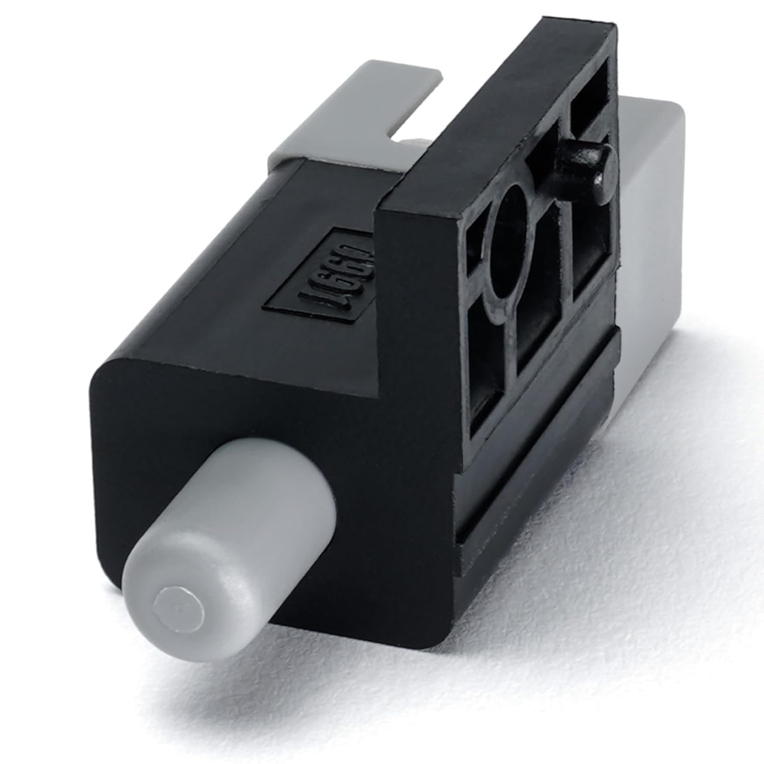
Figure 1: Side view of the HD Switch Safety Interlock Switch. This image displays the main body of the switch, featuring a grey push-button actuator extending from one end and the black housing with mounting points.

Figure 2: Connector end of the HD Switch Safety Interlock Switch. This view shows the electrical connection terminals, which are four flat metal prongs designed to plug into a corresponding harness.
The switch features a push-button actuator (Actuator Type: Push Button) and is designed for plug-in electrical connection (Connector Type: Plug In). It is typically mounted in a specific location on the equipment (Mounting Type: Wall Mount) to monitor a safety condition.
Setup and Installation
This safety interlock switch is an OEM replacement part. Follow the specific service manual for your Cub Cadet PRO Z series mower for detailed installation instructions. The general steps for replacement are as follows:
- Prepare Equipment: Ensure the mower is turned off, the engine is cool, and the spark plug wire is disconnected to prevent accidental starting.
- Locate Old Switch: Identify the existing safety interlock switch that needs replacement. Note its mounting location and how it is connected.
- Disconnect Wiring: Carefully disconnect the electrical connector from the old switch.
- Remove Old Switch: Unmount the old switch from its position. This may involve removing screws, clips, or releasing a snap-fit mechanism.
- Install New Switch: Position the new HD Switch Safety Interlock Switch in the exact location of the old one. Secure it using the original mounting hardware or integrated clips.
- Connect Wiring: Reconnect the electrical harness to the new switch's terminals. Ensure a secure and proper connection.
- Test Functionality: Before fully reassembling the mower, perform a functional test of the switch as described in the "Operating Principle" section to confirm correct installation.
- Reassemble: Reassemble any covers or components removed during the installation process.
Operating Principle
The safety interlock switch operates as a critical part of your mower's safety system. Its primary function is to ensure that certain conditions are met before the engine can start or continue to run. For example, it may prevent the engine from starting if:
- The operator is not seated (for seat switches).
- The parking brake is not engaged.
- The PTO (Power Take-Off) is engaged.
- A safety guard or shield is not in its proper position.
When the required safety condition is met, the switch allows the electrical circuit to complete, enabling the mower to operate. If the condition is not met, the switch interrupts the circuit, preventing operation or shutting down the engine, thereby enhancing user safety.
Maintenance
Regular inspection and basic maintenance can extend the life of your safety interlock switch and ensure continued safe operation of your equipment.
- Visual Inspection: Periodically inspect the switch for any visible signs of wear, damage, or corrosion, especially around the actuator and electrical connections.
- Cleanliness: Keep the area around the switch clean and free of debris, dirt, grass clippings, or moisture that could interfere with its operation. Use a dry cloth or compressed air for cleaning.
- Connection Integrity: Ensure that the electrical connector remains firmly attached to the switch. A loose connection can lead to intermittent operation or failure.
- Functionality Check: Regularly test the switch's functionality as part of your routine equipment checks. Refer to your mower's owner's manual for specific safety system test procedures.
Do not attempt to modify or bypass the safety interlock switch. This is a critical safety device and tampering with it can lead to serious injury.
Troubleshooting
If your equipment is not starting or operating as expected, and you suspect the safety interlock switch, consider the following common issues:
- Equipment Not Starting:
- Ensure all safety conditions are met (e.g., operator seated, PTO disengaged, parking brake on).
- Check the electrical connection to the switch for looseness or corrosion.
- Inspect the switch actuator for obstructions or damage that prevent it from engaging properly.
- Intermittent Operation:
- This often indicates a loose electrical connection or a switch that is beginning to fail. Re-seat the connector.
- Check for excessive vibration that might affect the switch's internal components or connections.
- Switch Appears Damaged:
- If the switch housing is cracked, the actuator is bent, or terminals are corroded, the switch needs to be replaced.
If troubleshooting steps do not resolve the issue, it is recommended to consult a qualified service technician or replace the switch.
Specifications
| Attribute | Detail |
|---|---|
| Brand | HD Switch |
| Product Type | Safety Interlock Switch |
| Connector Type | Plug In |
| Mounting Type | Wall Mount |
| Actuator Type | Push Button |
| Unit Count | 1.0 Count |
| Compatible Models | Cub Cadet PRO Z 500, 700, 900 Series (e.g., 554-L, 548-L, 560-L, 760-L, 772-L, 960-L, 960-S, 972-L, 972-S, KH EFI KW Models) |
Warranty and Support
For information regarding warranty coverage or technical support for your HD Switch Safety Interlock Switch, please contact the manufacturer directly. Refer to the packaging or the point of purchase for contact details. When contacting support, please have your product model information ready.
Manufacturer: HD Switch


