1. Introduction
The LILYGO T5 4.7 Inch E-Paper V2.3 ESP32-S3 Development Driver Board is a versatile module designed for various development and display applications. It integrates an ESP32-S3 microcontroller with Wi-Fi and Bluetooth V5.0 connectivity, paired with a low-power 4.7-inch e-paper display. This manual provides essential information for setting up and operating your device.
2. Key Features
- MCU: ESP32-S3-WROOM-1-N1 6R8
- Wireless Connectivity: Wi-Fi, Bluetooth V5.0
- Display: 4.7-inch Ultra-low Power E-paper (Driver IC: ED047TC1)
- Display Resolution: 540 x 960 pixels, 16 Gray levels
- Memory: 16MB Flash, 8MB PSRAM
- Additional Features: Support TF card, PCF8563 RTC, Battery capacity detection
- Dimensions: 4.68 x 2.44 x 0.31 inches
3. Package Contents

Image showing the LILYGO T5 4.7 Inch E-Paper V2.3 ESP32-S3 Development Board along with its accessories.

The development board and accessories are shown inside a protective plastic case.
- 1 x LILYGO T5 4.7 Inch E-Paper V2.3 ESP32-S3 Development Board
- 1 x GROVE Interface Cable
- 1 x Power Cable
- 1 x Female Pin 2*20p Header
4. Hardware Overview

Top view of the LILYGO T5-4.7-S3 board, highlighting the ESP32-S3 module, USB-C port, and various connectors.

The 4.7-inch E-Paper display, showcasing its low power consumption and high readability.

Dimensions of the LILYGO T5-4.7-S3 board.
Detailed pinout diagram of the LILYGO T5-4.7-S3 E-Paper board.
The board features a Type-C USB port for power and data transfer, a JST-GH 1.25mm 2-pin battery interface, and GPIO pin extension definitions. It also reserves a JST-SH 1.0mm 4-pin interface for STEMMA QT/Qwiic compatibility.
5. Setup and Getting Started
5.1. Entering Download Mode
To flash new firmware onto the board, you need to enter download mode. This typically involves a sequence of button presses:
- Connect the board to your computer via the USB-C cable.
- Press and hold the BOOT button.
- While holding BOOT, briefly press the RESET button.
- Release the RESET button.
- Release the BOOT button.
The board is now in download mode and ready for firmware upload.
Video demonstrating how to unpack the product, connect the battery, and enter download mode (from 0:09 to 2:50).
5.2. Development Environments
The LILYGO T5-4.7-S3 board supports various development environments. Refer to the official documentation and community resources for detailed setup instructions for each.
- PlatformIO: Installation and burning firmware using PlatformIO IDE for VS Code.
- Arduino IDE: Installation and burning firmware using Arduino IDE.
- MicroPython: Flashing MicroPython firmware onto the board.
- ESP-IDF: Setting up the ESP-IDF environment and flashing firmware.
Video demonstrating the process of flashing firmware using PlatformIO, Arduino IDE, and MicroPython/ESP-IDF (from 2:51 to 24:08 of the product introduction video, or the dedicated 'Flash Factory' video).
5.3. WiFi Configuration
To connect your device to a WiFi network, you can use the EspTouch app. Note that only 2.4GHz WiFi networks are supported.
- Download the EspTouch app on your smartphone (available for iOS and Android).
- Open the app and enter your 2.4GHz WiFi network name (SSID) and password.
- Ensure your LILYGO T5 board is in WiFi configuration mode (as indicated on its screen).
- Start the configuration process in the app. The board should connect to your WiFi network.
Once connected, the board can automatically synchronize time or display other network-dependent information.
Video demonstrating WiFi function and automatic time synchronization (from 0:58 to 1:20).
6. Basic Operation
The LILYGO T5-4.7-S3 board can display various information on its e-paper screen. Examples include a clock, WiFi status, battery level, and custom images. The onboard buttons can be programmed for custom functions, such as resetting the device or triggering specific display changes.
Video demonstrating automatic time synchronization and custom button functionality (from 1:10 to 1:50).
7. Specifications
| Feature | Detail |
|---|---|
| MCU | ESP32-S3-WROOM-1-N1 6R8 |
| Wireless Connectivity | Wi-Fi, Bluetooth V5.0 |
| Display Type | 4.7-inch E-Paper |
| Display Resolution | 540 x 960 pixels |
| Gray Levels | 16 |
| Flash Memory | 16 MB |
| PSRAM | 8 MB |
| RTC | PCF8563 |
| Battery Interface | JST-GH 1.25mm 2-pin |
| Dimensions (LxWxH) | 4.68 x 2.44 x 0.31 inches |
| Item Weight | 2.88 ounces |
8. Troubleshooting

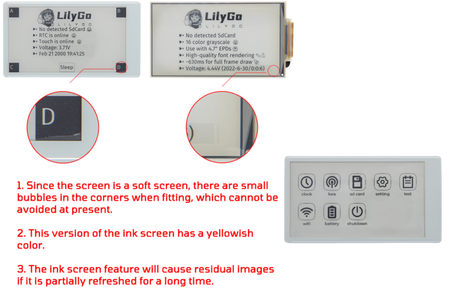
Visual examples of common e-paper display characteristics.
- Screen Bubbles: Small bubbles in the corners of the screen are a characteristic of soft e-paper displays and are currently unavoidable.
- Yellowish Tint: This version of the ink screen may exhibit a yellowish color.
- Residual Images: The ink screen feature may cause residual images if partially refreshed for a long time. This is normal behavior for e-paper technology.
- Connectivity Issues: Ensure correct drivers are installed for the USB-C port. Verify the correct COM port is selected in your development environment.
- Firmware Upload Failure: Double-check that the board is in download mode before attempting to upload firmware.
9. Support & Resources
For further technical support, code examples, and community discussions, please refer to the official LILYGO GitHub repository: