1. Product Overview
The CNAODUN PID Temperature Controller Kit A8-1 is designed for precise temperature regulation in various applications. This kit includes a PID temperature controller, a 40DA solid state relay (SSR), a K-type thermocouple probe, and a heat sink for the SSR. It operates on 100-240 VAC power and offers features such as adjustable Fahrenheit/Celsius display and alarm outputs.
Kit Contents:
- PID Temperature Controller (Model A8-1)
- 40DA Solid State Relay (SSR)
- K-Type Thermocouple Probe
- Heat Sink for SSR
- Mounting Screws and Thermal Compound

2. Setup and Installation
2.1 Mounting the Controller
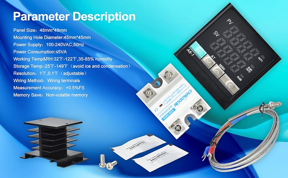
The A8-1 controller is designed for panel mounting. Ensure the panel cutout dimensions are 45mm x 45mm (1.77 inches x 1.77 inches) for a secure fit. The controller's front panel measures 48mm x 48mm (1.89 inches x 1.89 inches).

2.2 Solid State Relay (SSR) and Heat Sink Installation
The 40DA Solid State Relay (SSR) controls the heating element. It is crucial to mount the SSR onto the provided heat sink to dissipate heat and prevent overheating. Apply a thin, even layer of the included thermal compound between the SSR and the heat sink before securing them with screws.


2.3 Wiring Diagram
Refer to the wiring diagram below for proper connection of the PID controller, SSR, heating element (or fan), and thermocouple. Ensure all connections are secure and correctly polarized. Incorrect wiring can damage the device or pose a safety hazard.
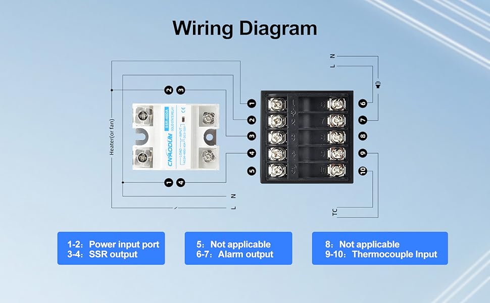
- Power Input (Terminals 1-2): Connect 100-240 VAC power supply.
- SSR Output (Terminals 3-4): Connect to the input terminals of the 40DA Solid State Relay.
- Alarm Output (Terminals 6-7): These are AC220V/DC30V 3A (Resistive load) ON/NC outputs, which can be used to connect an external alarm or relay.
- Thermocouple Input (Terminals 9-10): Connect the K-type thermocouple probe. The controller supports K, E, J, N, W3-25, W5-26 type thermocouples and PT100, Cu50 inputs. The default setting is K-type.
- SSR Load Connection: Connect the heating element (or fan) to the load terminals of the SSR. The SSR's input is controlled by the PID controller's output.

3. Operating Instructions
3.1 Front Panel Overview
The controller features a dual digital display and several control buttons.

- PV Display: Shows the current measured temperature value and various prompts based on instrument status.
- SV Display: Shows the set temperature value and various parameter values.
- Indicator Lights:
- OUT1: Heating indicator, illuminates when output is active.
- OUT2: Refrigeration indicator, illuminates when output is active (if configured).
- ALM1: Upper limit alarm, illuminates when alarm condition is met.
- ALM2: Lower limit alarm, illuminates when alarm condition is met.
- Shift Key (<): Used to shift digits when adjusting values.
- Add Key (▲): Increases adjustment values, enters manual mode, or switches menus/parameters.
- Minus Key (▼): Decreases adjustment values, initiates self-tuning, or switches menus/parameters.
- Function Key (SET): Enters main menu and sub-menu, modifies parameters, and confirms settings.
3.2 Setting the Temperature (SV)
To set the desired temperature (SV):
- Press the SET key briefly. The SV display will begin to flash.
- Use the ▲ (Add) and ▼ (Minus) keys to adjust the value. Use the < (Shift) key to move between digits for faster adjustment.
- Press the SET key again to confirm the new SV and exit the setting mode.
3.3 PID Auto-Tuning (AT)
The controller features an auto-tuning function to optimize PID parameters for your specific system. To initiate auto-tuning:
- Set the desired temperature (SV) first.
- Press and hold the ▼ (Minus) key for a few seconds until the AT indicator light illuminates. The controller will cycle through heating and cooling to determine optimal PID values.
- Once auto-tuning is complete, the AT indicator light will turn off, and the controller will operate with the newly calculated PID parameters.
3.4 Parameter Adjustment (Fahrenheit/Celsius, Input Type)
To access advanced parameters, including temperature unit (℉/℃) and sensor input type:
- Press and hold the SET key for several seconds to enter the main parameter menu.
- Use the ▲ (Add) and ▼ (Minus) keys to navigate through the parameters.
- Press SET to select a parameter, then use ▲ and ▼ to change its value.
- Press SET again to confirm the change and move to the next parameter or exit the sub-menu.
- To exit the parameter menu, continue pressing SET until the controller returns to the normal display, or wait for a timeout.
Note: The default temperature unit is Fahrenheit. The default sensor input is K-type thermocouple. Consult the full manual for a complete list of parameters and their functions.
4. Maintenance
To ensure optimal performance and longevity of your PID Temperature Controller Kit:
- Cleaning: Keep the controller's display and buttons clean using a soft, dry cloth. Avoid abrasive cleaners or solvents.
- Environment: Operate the controller within the specified operating temperature and humidity ranges (see Specifications). Avoid exposure to excessive dust, moisture, or corrosive gases.
- Connections: Periodically check all wiring connections for tightness and signs of wear or corrosion.
- Heat Sink: Ensure the SSR heat sink remains free of obstructions to allow for proper airflow and heat dissipation.
5. Troubleshooting
If you encounter issues with your PID Temperature Controller Kit, consider the following:
- No Power/Display:
- Check the power supply connection (Terminals 1-2) and ensure the voltage is within 100-240 VAC.
- Verify that the power source is active.
- Incorrect Temperature Reading (PV):
- Ensure the thermocouple is correctly connected to Terminals 9-10 and is not damaged.
- Verify that the thermocouple type set in the controller's parameters matches the installed K-type probe.
- Check for proper contact between the thermocouple and the measured object.
- No Output to Heating Element:
- Check the wiring between the controller's SSR output (Terminals 3-4) and the SSR input.
- Verify the wiring between the SSR load terminals and the heating element.
- Ensure the set temperature (SV) is above the current temperature (PV) if in heating mode.
- Check the SSR for proper function.
- Controller Not Responding to Settings:
- Ensure you are correctly using the SET, ▲, ▼, and < keys as described in Section 3.
- If parameters are locked, consult the full manual for unlocking procedures.
6. Specifications
Detailed technical specifications for the CNAODUN PID Temperature Controller Kit A8-1.
| Feature | Specification |
|---|---|
| Model | A8-1 |
| Panel Size | 48mm x 48mm (1.89 x 1.89 inches) |
| Mounting Hole Diameter | 45mm x 45mm (1.77 x 1.77 inches) |
| Power Supply Voltage | 100-240 VAC, 50/60Hz |
| Power Consumption | ≤5VA |
| Working Temperature & Humidity | 32°F ~ 122°F (0°C ~ 50°C), 35-85% RH (non-condensing) |
| Storage Temperature | -25°F ~ 149°F (-31°C ~ 65°C) (avoid ice and condensation) |
| Resolution | 1°F / 0.1°F (adjustable) |
| Measurement Accuracy | ±0.5% FS (Full Scale) |
| Wiring Method | Wiring terminals |
| Memory | Non-volatile memory |
| SSR Output | 3,4 port output to SSR (40DA Solid State Relay included) |
| Alarm Output | 6,7 ports, AC220V/DC30V 3A (Resistive load) ON/NC |
| Sensor Input | 3-wire or 2-wire sensor input; K, E, J, N, W3-25, W5-26 type thermocouple; PT100, Cu50 (Default: K-type thermocouple) |
| Display Type | LCD Digital Display (PV and SV simultaneously) |
| Item Weight (Kit) | 11.3 ounces (320 grams) |
7. Warranty and Support
Information regarding product warranty and customer support was not provided in the available product data. Please refer to the product packaging or contact the manufacturer directly for details on warranty coverage and technical assistance.