1. Introduction
This manual provides essential information for the safe and effective installation, operation, and maintenance of the Hayward Universal HC Series Dual-Fuel Gas Heater Ignition Control Board, model HDXFICBRD001. This control board is a critical component designed to manage the ignition sequence and overall operation of compatible Hayward gas heaters, ensuring reliable and efficient performance. Please read this manual thoroughly before attempting any installation or service.
2. Important Safety Information
WARNING: Improper installation, adjustment, alteration, service, or maintenance can cause property damage, injury, or death. Read the installation, operating, and maintenance instructions thoroughly before installing or servicing this equipment.
- Always disconnect power to the heater before installing or servicing the control board.
- Installation and service must be performed by a qualified installer, service agency, or gas supplier.
- Ensure all wiring connections comply with local codes and regulations.
- Do not operate the heater if any part has been submerged in water. Immediately call a qualified service technician to inspect the heater and replace any part of the control system and gas control that has been submerged in water.
- Handle the control board with care to avoid electrostatic discharge, which can damage electronic components.
3. Product Overview
The HDXFICBRD001 is the central control unit for the ignition and operational functions of Hayward Universal HC Series Dual-Fuel Gas Heaters. It manages the ignition sequence, monitors safety limits, and processes sensor inputs to ensure safe and efficient heating.

This image displays the top side of the Hayward HDXFICBRD001 Ignition Control Board, featuring integrated circuits, resistors, capacitors, relays, and various connection terminals for power, sensors, and ignition components. Key labels such as '120 VAC', 'PS/LIMITS', 'TEMP. SENSE', 'FLAME SENSOR', and 'IGNITOR' are visible, indicating connection points for the heater system.
4. Installation Instructions
Installation of the HDXFICBRD001 Ignition Control Board should only be performed by a qualified service technician. Incorrect installation can lead to heater malfunction, property damage, or personal injury.
4.1 Pre-Installation Steps
- Disconnect Power: Ensure all electrical power to the heater is completely disconnected at the main breaker.
- Shut Off Gas Supply: Close the manual gas shut-off valve to the heater.
- Access Control Panel: Open the heater's control panel to gain access to the existing ignition control board.
- Document Connections: Take clear photographs or make detailed diagrams of all existing wiring connections to the old control board. Label each wire and its corresponding terminal.
4.2 Removal of Old Board
- Carefully disconnect all wires from the old control board, referring to your documentation.
- Unscrew or unclip the old board from its mounting points.
4.3 Installation of New Board
- Position the new HDXFICBRD001 board in the heater's control panel.
- Secure the board using the appropriate screws or clips. Ensure it is firmly mounted.

This image shows the reverse side of the Hayward HDXFICBRD001 Ignition Control Board, protected by a white plastic mounting bracket. The bracket is designed to secure the board within the heater unit, and the visible solder points indicate the connections for the electronic components on the front side.
- Reconnect all wires to the new control board, matching them to the labels and documentation created during pre-installation. Pay close attention to power, sensor, and ignitor connections.

This close-up image focuses on the power input and limits section of the Hayward HDXFICBRD001 Ignition Control Board. Connectors for '120 VAC N H Gnd' and 'PS/LIMITS R E2 C E3 S18' are clearly visible, along with a fuse (3A) and various resistors and relays, indicating the power supply and safety limit switch connections.
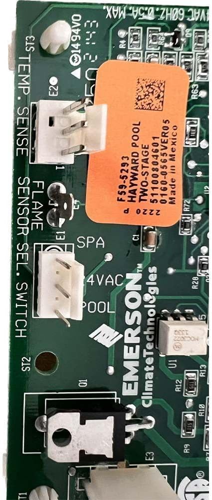
This image provides a detailed view of the sensor and switch connection area on the Hayward HDXFICBRD001 Ignition Control Board. Labels such as 'TEMP. SENSE', 'FLAME SENSOR', and 'SENSOR SEL. SWITCH' are visible, indicating the inputs for temperature and flame detection, crucial for safe and efficient heater operation. An orange sticker with product information is also present.

A close-up shot of the Hayward HDXFICBRD001 Ignition Control Board, specifically showing the 'IGNITOR' connection point (ST1). This is where the ignitor component of the gas heater connects to receive the signal for initiating combustion.

A detailed view of a section of the Hayward HDXFICBRD001 Ignition Control Board, highlighting specific connectors labeled 'XFMR NEUT H' and 'ST5'. A barcode sticker is visible on one of the connectors, likely for identification purposes. This area manages transformer and neutral connections.
4.4 Post-Installation Steps
- Verify Connections: Double-check all wiring connections for tightness and correctness.
- Restore Gas Supply: Slowly open the manual gas shut-off valve.
- Restore Power: Turn on the electrical power to the heater at the main breaker.
- Test Operation: Follow the heater's user manual to initiate a heating cycle and observe for proper ignition and operation.
5. Operating Principles
The HDXFICBRD001 Ignition Control Board operates by receiving a call for heat from the heater's thermostat or control panel. Upon receiving this signal, it initiates a pre-purge cycle, followed by energizing the ignitor and opening the gas valve. The board continuously monitors the flame presence through the flame sensor. If a flame is not detected within a specified time, or if the flame is lost during operation, the board will safely shut down the gas supply and attempt to re-ignite or enter a lockout state, depending on the specific error condition.
6. Maintenance
The HDXFICBRD001 Ignition Control Board is designed for reliable operation and generally requires minimal maintenance. However, periodic inspection of the heater system is recommended.
- Visual Inspection: Annually inspect the control board and its connections for any signs of corrosion, loose wires, or physical damage.
- Cleanliness: Ensure the area around the control board is free from dust, debris, and moisture. Use a soft, dry brush or compressed air to gently clean the board if necessary, with power disconnected.
- Professional Check: It is recommended to have a qualified service technician perform a comprehensive inspection of your heater system, including the control board, at least once a year.
7. Troubleshooting
If your heater is not operating correctly, the control board may display error codes to indicate a problem. Refer to the heater's main user manual for a complete list of error codes and their specific troubleshooting steps. Below are common error codes related to the ignition control board itself:
7.1 Error Codes
- EE - EEPROM error: An error was detected in the ignition control board's EEPROM (Electrically Erasable Programmable Read-Only Memory). This indicates an internal fault with the board's memory.
- b1 - Ignition control board data error: If the ignition control board does not satisfy self-diagnostic on power up or initial trial for ignition, the ignition control board will lockout until the error condition is corrected. This suggests a failure during the board's internal self-test or initial startup sequence.
7.2 General Troubleshooting Steps
- Power Cycle: Disconnect power to the heater for 5 minutes, then restore power. This can sometimes reset the board and clear temporary errors.
- Check Connections: Ensure all wires connected to the control board are secure and correctly seated. Loose connections can cause intermittent issues.
- Inspect for Damage: Visually inspect the board for any signs of burning, corrosion, or physical damage.
- Consult Heater Manual: Refer to your specific Hayward heater's instruction manual for detailed troubleshooting guides related to ignition and control system faults.
- Professional Assistance: If error codes persist or the heater fails to operate correctly after basic troubleshooting, contact a qualified service technician.
8. Specifications
| Model Number | HDXFICBRD001 |
| Product Dimensions | 27 x 17 x 17.2 inches |
| Item Weight | 15 pounds |
| Manufacturer | Hayward-Pool |
9. Warranty Information
For specific warranty terms and conditions pertaining to the Hayward Universal HC Series Dual-Fuel Gas Heater Ignition Control Board HDXFICBRD001, please refer to the warranty documentation provided with your original heater unit or contact Hayward customer support directly. Keep your proof of purchase for warranty claims.
10. Customer Support
If you require further assistance, have questions regarding installation, operation, or troubleshooting, please contact Hayward customer support. Have your product model number (HDXFICBRD001) and heater serial number ready when you call.
Hayward Official Website: www.hayward-pool.com


