1. Introduction
This manual provides essential information for the setup, operation, and maintenance of your Nextion 10.1-inch Intelligent Series HMI Display (Model: NX1060P101-011R-I). This resistive LCD-TFT touch screen features a 1024x600 resolution and is designed for a wide range of applications, including IoT smart devices, 3D printers, and industrial control systems. It supports advanced functions such as video, audio, and animation playback.

Figure 1: Nextion 10.1-inch HMI Display with example UI.
2. Product Overview
2.1 Key Features
- Display Size: 10.1 inches
- Resolution: 1024x600 pixels
- Color Depth: RGB 65K true-to-life colors
- Touch Type: Resistive LCD-TFT
- Onboard MCU: 200 MHz
- Memory: 128MB Flash, 512KB SRAM, 1024 Byte EEPROM
- Connectivity: TTL Serial (+5V, TX, RX, GND)
- Additional Features: 8 GPIOs, Real-Time Clock (RTC), SD card slot, Audio Interface
2.2 Components in the Box
The product package includes the following items:
- Nextion 10.1-inch HMI Display (NX1060P101-011R-I) x1
- XH2.54 4P Wire x1
- Power Supply Test Board x1

Figure 2: Included components.
2.3 Internal Components Overview
The internal architecture of the Nextion Intelligent Series HMI Display includes several key components for its functionality:
- MCU: Integrated with SRAM and Touch Controller.
- Flash Storage & EEPROM: For program and data storage.
- GPIOs: General Purpose Input/Output pins for external connections.
- RTC: Real-Time Clock for timekeeping.
- SD Card Slot: For additional storage and firmware updates.
- Audio Interface: For audio output capabilities.
- TTL Serial: (+5V, TX, RX, GND) for communication with external microcontrollers.
Video 1: Overview of Nextion Intelligent Series Display internal components and applications.
3. Setup
3.1 Powering the Display
The Nextion HMI Display requires a 5V DC power supply. You can power the display using the provided XH2.54 4P wire and Power Supply Test Board, connected to a standard 5V USB power adapter.
- Connect the XH2.54 4P wire to the corresponding port on the back of the Nextion display.
- Connect the VCC wire (typically red) to the '+' terminal and the GND wire (typically black) to the '-' terminal on the Power Supply Test Board.
- Connect a micro USB cable to the Power Supply Test Board.
- Plug the micro USB cable into a 5V 2A power supply adapter.
- Power on the adapter to energize the display.
Video 2: Instructions on how to power the Nextion Display via Micro USB 5V.
3.2 Connecting to a Microcontroller
To communicate with an external microcontroller (e.g., Arduino, ESP32), use the TTL serial interface. Connect the TX pin of the display to the RX pin of your microcontroller, and the RX pin of the display to the TX pin of your microcontroller. Ensure both devices share a common ground (GND) and are powered correctly.
4. Operating Instructions
4.1 User Interface Design with Nextion Editor
The Nextion HMI Display is programmed using the Nextion Editor software. This software allows you to design graphical user interfaces (GUIs) by dragging and dropping components, setting attributes, and writing simple event-driven code. Key features of the Nextion Editor include:
- Versatile Character Encoding
- Fonts and Text Styling
- Over 25 WYSIWYG (What You See Is What You Get) Components
- Component Attribute Setting
- Free Simulator for Debugging
- Nextion Operational Commands
- Text-based Instruction Set
- Support for Simple Assignment Operators

Figure 3: Nextion Editor Features.
4.2 Uploading Your Project
Once your GUI project is complete in the Nextion Editor, you can upload it to the display via the serial port or an SD card. Refer to the Nextion Editor documentation for detailed upload procedures.
5. Applications
The Nextion 10.1-inch Intelligent Series HMI Display is versatile and can be integrated into various systems:
- IoT Smart Devices: Control and monitor smart home appliances or industrial IoT solutions.
- 3D Printers: Provide an intuitive touch interface for controlling printer operations.
- Medical Devices: Display critical data and allow user interaction in medical equipment.
- Industrial Control: Serve as a human-machine interface for machinery and automation systems.
- Automotive Dashboards: Enhance user experience with interactive displays for vehicle information.

Figure 4: Applications in IoT, Medical, and Beauty Devices.
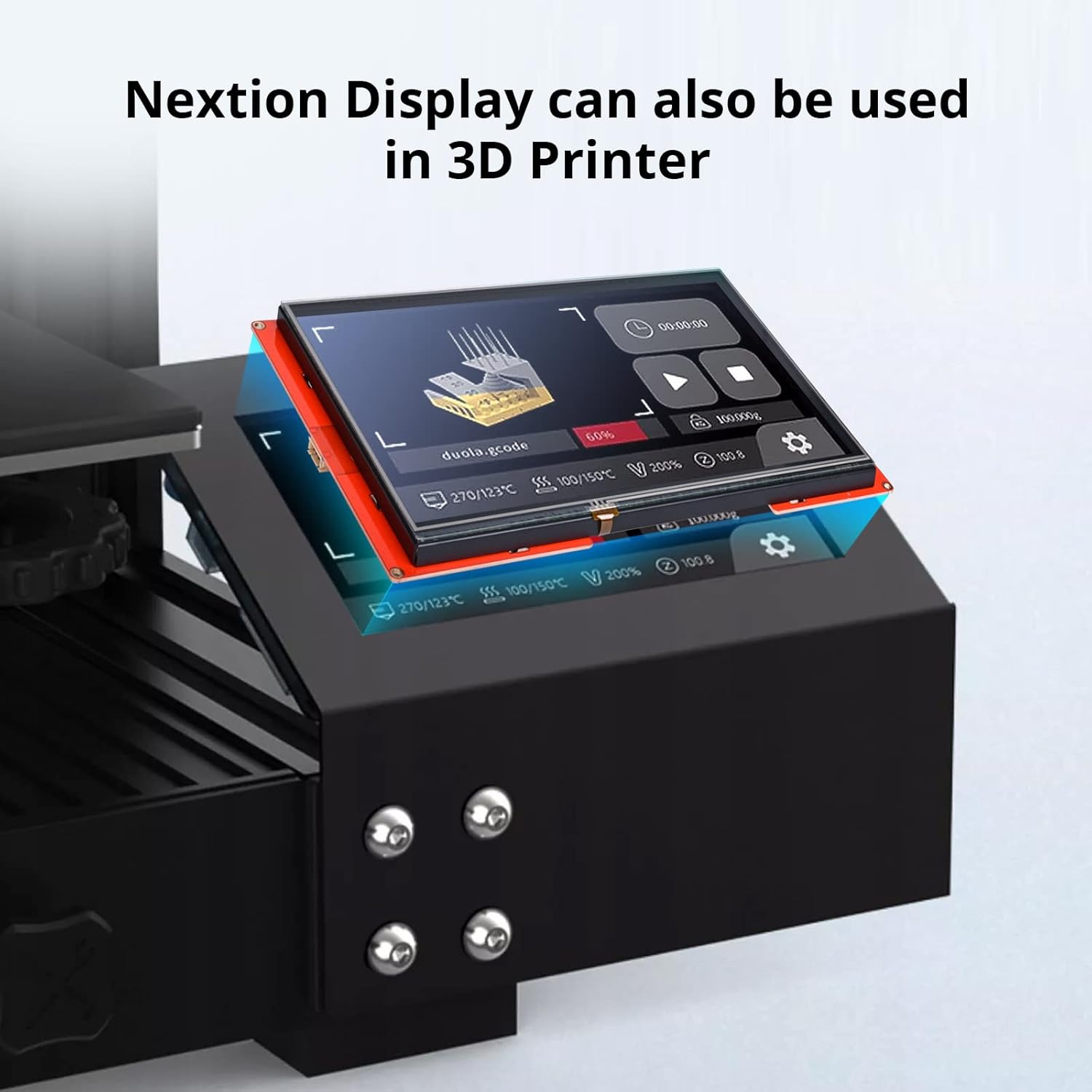
Figure 5: Nextion Display as a 3D printer interface.
Video 3: Demonstrates various UI examples and applications of the Nextion Intelligent Series Display.
6. Specifications
| Feature | Specification |
|---|---|
| Model Name | NX1060P101-011R-I |
| Display Size | 10.1 inch |
| Resolution | 1024*600 |
| Touch Panel | Resistive (RTP) |
| MCU | 200 MHz |
| Flash Memory | 128 MB |
| SRAM | 512KB |
| EEPROM | 1024 Byte |
| GPIOs | 8 |
| RTC (Real-Time Clock) | Yes |
| Operating System Compatibility | Windows, Linux, macOS |
| Item Weight | 1.57 pounds |
| Product Dimensions | 10.16 x 5.98 x 0.71 inches |
Table 1: Product Specifications.
7. Troubleshooting
Encountering issues? Here are some common problems and their potential solutions:
- Display Not Powering On: Ensure the 5V power supply is correctly connected and providing sufficient current (minimum 1A). Verify cable connections.
- No Communication with Microcontroller:
- Check TX/RX wiring (TX to RX, RX to TX).
- Ensure common ground connection.
- Verify baud rates match between the display and microcontroller.
- If using a USB-to-serial converter, ensure the correct CH340 driver is installed on your computer.
- Garbled Text on Serial Monitor: This typically indicates a mismatch in baud rates. Ensure the baud rate set in your code matches the baud rate selected in your serial monitoring software.
- Nextion Editor Learning Curve: The Nextion Editor has a learning curve. Utilize online tutorials, community forums, and the official documentation for guidance.
- Over-voltage Damage: The display operates on 5V only. Connecting a higher voltage power supply (e.g., 9V) will damage the unit. Always verify your power source.
- Dual-State Button Behavior: If dual-state buttons reset when changing screens, ensure the variable scope for the button is set to global (it is local by default).
- ESP32 Development Environment Issues: When developing with ESP32, ensure you install ESP32 package version 2.0.14 or 2.0.15 in the Arduino IDE. Other versions may cause compilation or runtime errors. Also, configure the PSRAM option (QSPI PSRAM for 4.3-inch, OPI PSRAM for 5-inch/7-inch) and select a suitable Partition Scheme (e.g., 'Huge APP') if needed.
8. Maintenance
To ensure the longevity and optimal performance of your Nextion HMI Display, follow these maintenance guidelines:
- Cleaning: Use a soft, lint-free cloth to gently wipe the screen. Avoid abrasive materials or harsh chemical cleaners that could damage the resistive touch layer.
- Power Supply: Always use a stable 5V DC power supply. Avoid voltage fluctuations or connecting incorrect power sources.
- Environmental Conditions: Operate the display within its specified temperature and humidity ranges. Avoid extreme temperatures, direct sunlight, and high moisture environments.
- Handling: Handle the display with care to prevent physical damage to the screen or circuit board.
9. Warranty and Support
NEXTION is committed to providing reliable products. The Intelligent Series HMI Displays are designed with a 5-year Long Term Availability (LTA), ensuring product availability for at least five years from the date of purchase.
For technical support, documentation, software downloads, and community forums, please visit the official NEXTION website or their brand store on Amazon. Detailed resources are available to assist with project development and troubleshooting.
For further assistance, please refer to the NEXTION Brand Store.


