Introduction
The Miuzei Electronics Component Fun Kit is designed to provide a comprehensive set of electronic components for learning and experimenting with basic to intermediate electronic projects. This kit is compatible with popular development platforms such as Arduino, Raspberry Pi, and STM32, making it an ideal resource for students, hobbyists, and educators. It includes a wide variety of sensors and components, allowing users to explore fundamental electronic principles and build diverse circuits.
Product Overview and Components
This kit contains over 400 individual electronic components, carefully selected and organized to facilitate various projects. Each component type is individually packaged and labeled for easy identification and storage within the provided sturdy plastic box.

Image: An overhead view of the Miuzei Electronics Component Fun Kit, displaying all included components neatly arranged on a flat surface. This includes breadboards, various resistors, LEDs, integrated circuits, potentiometers, jumper wires, and a power supply module.
Key Components Included:
- Breadboards: Two 830 tie-points solderless breadboards for prototyping circuits.
- Power Supply Module: A dedicated breadboard power supply module (6.5-9V DC input) with selectable 5V and 3.3V outputs, and a USB power input option.
- Jumper Wires: A variety of male-to-male and female-to-male jumper wires for connecting components on the breadboard.
- Resistors: A comprehensive assortment of resistors with various resistance values (e.g., 10R, 100R, 220R, 330R, 1K, 2K, 5.1K, 10K, 100K, 1M).
- LEDs: Multiple colored LEDs (White, Yellow, Blue, Green, Red) for visual indicators.
- Capacitors: Electrolytic capacitors (100uF 50V) and ceramic capacitors (104, 22pF).
- Transistors: NPN transistors (2N3904, PN2222) for amplification and switching.
- Diodes: Diode rectifiers (4148, 1N4007).
- Integrated Circuits (ICs): Including IC 74HC595 (shift register) and IC 4N35 (optocoupler).
- Potentiometers: 10K precision potentiometers for variable resistance.
- Displays: 1x 4-Digit 7-Segment Display and 7-Segment Displays.
- Sensors & Actuators: Active and Passive Buzzers, Buttons, Thermistors, Tilt Switch, Photoresistor.
- USB Cable: For powering the breadboard power supply module.

Image: A visual inventory of the Miuzei Electronics Component Fun Kit, showing the quantity and type of each component, such as breadboards, power supply module, USB cable, various resistors, LEDs, and integrated circuits.
Setup
Before beginning any project, ensure you have a clean and organized workspace. The components are delicate and should be handled with care.
- Unpack Components: Carefully remove components from their individual packaging. Keep them organized in the provided storage box to prevent loss or damage.
- Breadboard Familiarization: Understand the layout of the breadboard. The long horizontal rows (power rails) are typically used for power (+ and -), and the shorter vertical columns are for component connections.
- Power Supply Module Connection:
- Insert the breadboard power supply module into the power rails of your breadboard. Ensure it is firmly seated.
- Connect the provided USB power cable to the power supply module's USB input and to a suitable USB power source (e.g., computer USB port, USB wall adapter).
- Alternatively, a 9V 1A DC adapter (not included) can be used with the DC barrel jack input on the module.

Image: A close-up view of the breadboard power supply module, highlighting its input voltage range (6.5-9V DC), locking On/Off switch, LED power indicator, USB interface for external devices, and output header pins for 5V and 3.3V.

Image: An illustration showing the two power modes for the breadboard power supply: via a 9V 1A DC adapter (not included) or the included M/M USB power cable. The image emphasizes the flexibility in powering the module.
Operating Instructions
This kit is designed for hands-on learning. Below are general guidelines for using the components. For specific project instructions, refer to external tutorials and datasheets.
Using the Breadboard Power Supply:
- The power supply module provides stable 5V and 3.3V DC outputs, which are commonly used for microcontrollers and various electronic components.
- Use the jumpers on the module to select the desired voltage (5V or 3.3V) for each side of the breadboard's power rails.
- Always ensure the power supply is off before making or changing connections on the breadboard.
- Press the locking On/Off switch to power the breadboard. The LED power indicator will illuminate when power is active.
Basic Circuit Building with LEDs:
LEDs (Light Emitting Diodes) are polarized components, meaning they must be connected in the correct orientation.
- The longer leg of an LED is the anode (+) and should be connected to the positive voltage supply (e.g., 5V or 3.3V via a resistor).
- The shorter leg is the cathode (-) and should be connected to ground.
- Always use a current-limiting resistor in series with an LED to prevent it from burning out. Typical resistor values for 5V operation are 220 Ohm to 330 Ohm.
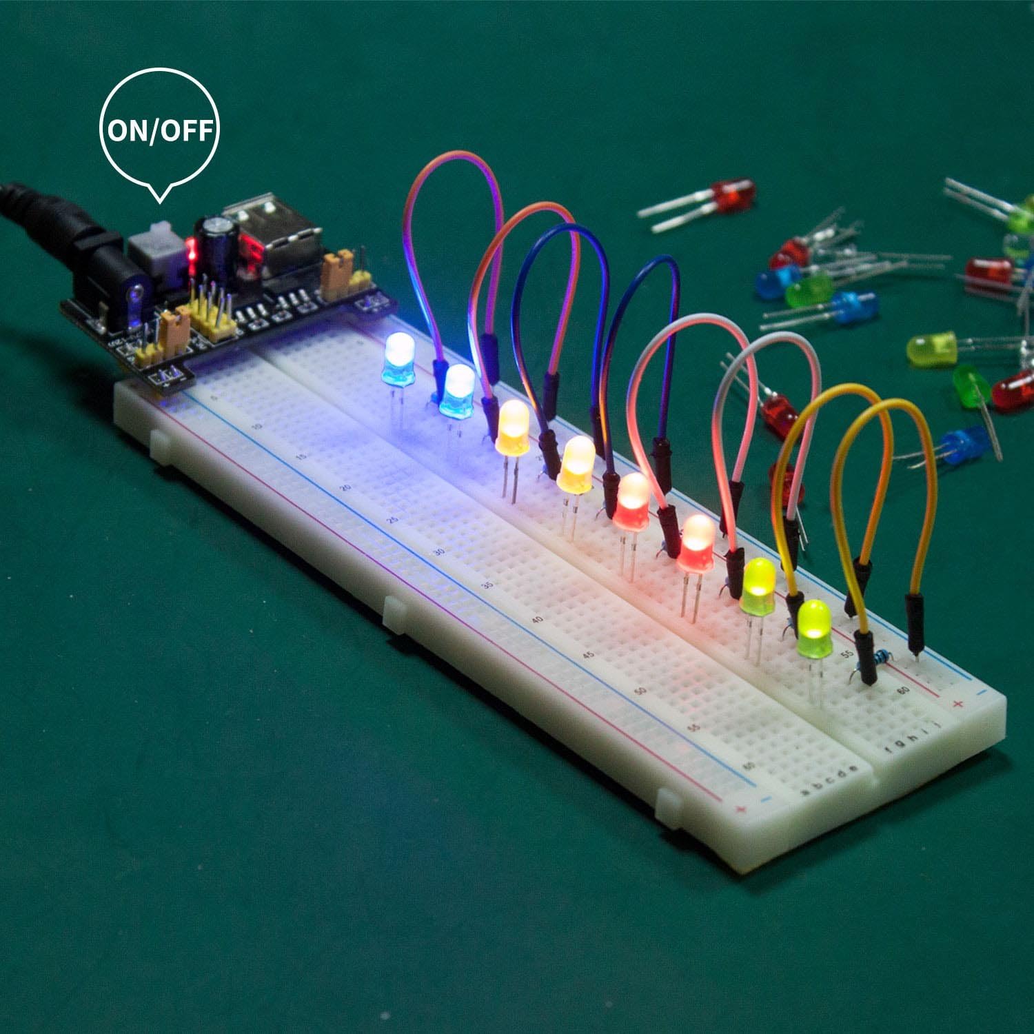
Image: An example circuit on a breadboard showing multiple colored LEDs illuminated, connected to the breadboard power supply module with jumper wires. This demonstrates a basic application of the kit's components.
Working with Resistors:
Resistors limit current flow in a circuit. Their value is indicated by color bands.
- Refer to a resistor color code chart to identify the resistance value of each resistor.
- Ensure the correct resistor value is used for each component to prevent damage or improper operation.
Using Jumper Wires:
Jumper wires are essential for making connections on the breadboard.
- Use male-to-male wires for connecting points on the breadboard.
- Use female-to-male wires for connecting breadboard points to pins on development boards (e.g., Arduino).
- Keep wire lengths as short as possible to maintain a tidy and reliable circuit.
Maintenance
Proper maintenance ensures the longevity and functionality of your electronic components.
- Storage: Always store components in the provided plastic case. This protects them from dust, moisture, and physical damage. The individual compartments help keep different component types separated and organized.
- Handling: Handle all components, especially integrated circuits and LEDs, by their bodies rather than their leads to prevent bending or damage.
- Cleanliness: Keep your workspace clean and free of debris. Dust and foreign particles can interfere with circuit connections.
- Power Off: Always disconnect power from the breadboard and power supply module when not in use or when making changes to the circuit.

Image: A comparison image highlighting the high-quality plastic box provided with the Miuzei kit for multiple storage options, contrasted with a generic kit that comes in an easily damaged paper box.
Troubleshooting
If your circuit is not functioning as expected, consider the following common issues:
- No Power:
- Ensure the breadboard power supply module is correctly inserted into the breadboard's power rails.
- Verify that the USB cable is securely connected to both the module and a working power source.
- Check if the On/Off switch on the power supply module is in the 'On' position and the power indicator LED is lit.
- LED Not Lighting Up:
- Polarity: Confirm the LED's longer leg (anode) is connected to positive voltage and the shorter leg (cathode) to ground (via a resistor).
- Resistor Value: Ensure you are using an appropriate current-limiting resistor (e.g., 220-330 Ohm for 5V). Too high a resistance will make the LED dim; too low can burn it out.
- Connection: Check for loose connections on the breadboard.
- Component Malfunction:
- Double-check the component's orientation (e.g., diodes, ICs, transistors).
- Ensure the component is correctly identified and matches the circuit diagram.
- Inspect components for any visible damage (e.g., bent pins, burn marks).
- Incorrect Wiring:
- Carefully review your circuit diagram and compare it to your physical breadboard setup.
- Ensure all jumper wires are making solid connections and are in the correct holes.
- Avoid short circuits, especially across power rails.
Specifications
| Feature | Detail |
|---|---|
| Brand | Miuzei |
| Model Number | B0BTHLML16 |
| Item Weight | 13.7 ounces |
| Package Dimensions | 8.78 x 7.09 x 2.32 inches |
| Breadboard Tie-Points | 830 (per breadboard) |
| Power Supply Module Input Voltage | 6.5-9V DC |
| Power Supply Module Output Voltage | 5V, 3.3V (selectable) |
| Compatibility | Arduino, Raspberry Pi, STM32 |
| Storage | Sturdy plastic box with compartments |
Support and Resources
For additional information, datasheets, and tutorials, please visit the official Miuzei website.
- Official Website: Miuzei Store on Amazon (for product information and updates)
- Datasheets & Tutorials: Specific datasheets and detailed tutorials for various components and projects can often be found on the manufacturer's support pages or reputable electronics learning platforms.


