
1. Introduction
This manual provides essential information for the safe and effective operation of your UEi Test Instruments DL569 400A Dual Display Clamp Meter. Please read this manual thoroughly before using the device and retain it for future reference. The DL569 is designed for professional use in electrical testing, offering a dual display for convenient readings of various electrical parameters.
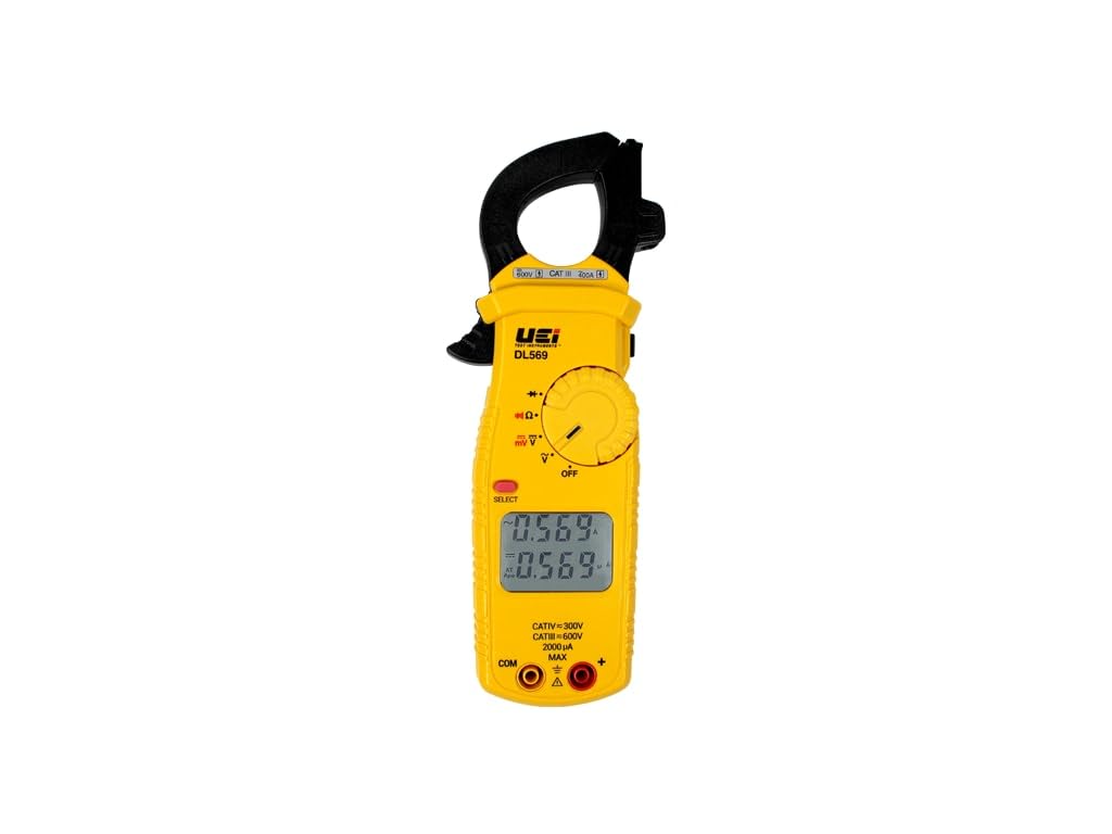
Figure 1: The UEi Test Instruments DL569 400A Dual Display Clamp Meter. This image shows the front view of the yellow clamp meter with its dual digital display, rotary dial, and measurement input jacks.
2. Safety Information
The DL569 clamp meter is safety rated CATIV 300V / CATIII 600V and certified by ETL to IEC 61010-1, 3rd edition. Adherence to safety guidelines is crucial to prevent electrical shock, injury, or damage to the meter. Always follow these precautions:
- Always inspect the meter, test leads, and accessories for any damage before use. Do not use if damaged.
- Ensure the function switch is set to the correct measurement range before connecting to a circuit.
- Do not exceed the maximum input limits for any function.
- Use caution when working with voltages above 30V AC RMS, 42V peak, or 60V DC, as these pose a shock hazard.
- Always wear appropriate personal protective equipment (PPE), such as safety glasses and insulated gloves.
- Do not operate the meter in wet environments or in the presence of explosive gases or dust.
- Replace batteries promptly when the low battery indicator appears to ensure accurate readings.
3. What's in the Box
Upon opening the package, verify that all items listed below are present and undamaged:
- DL569 Dual Display Clamp Meter
- Test Leads (ATL55)
- Alligator Clips
- AAA Batteries (Quantity: 2)
- Pouch/Case
- Instruction Manual (this document)

Figure 2: The DL569 Clamp Meter shown with its standard accessories, including test leads, alligator clips, batteries, and a protective carrying pouch.
4. Product Features
The DL569 clamp meter offers a range of features designed for efficiency and accuracy:
- Dual Display Screen: Provides simultaneous readings, with Amps (AC/DC) always displayed on the upper screen for easy monitoring.
- NCV Detection Function: Non-contact voltage detection allows for checking electrical status by measuring electromagnetic field intensity without direct contact with wires.
- Comprehensive Measurement Functions: Measures AC Volts (750VAC), DC Volts (1000VDC), AC Current (400A AC), AC Micro Volts (400mV), Resistance (10MOhms). Includes Continuity and Diode test functions.
- Integrated Test Lead Storage: Conveniently store test leads directly on the meter for easy access and organization.

Figure 3: A close-up view of the DL569's dual digital display, showing simultaneous readings for different parameters, enhancing user convenience.

Figure 4: Detail of the integrated test lead storage on the back of the DL569 meter, designed for secure and convenient organization of test leads.
5. Setup
5.1 Battery Installation
- Locate the battery compartment on the rear of the meter.
- Use a screwdriver to open the battery cover.
- Insert two AAA batteries, ensuring correct polarity (+/-).
- Replace the battery cover and secure it with the screw.
5.2 Initial Inspection
Before each use, perform a visual inspection of the meter, test leads, and accessories for any signs of damage, cracks, or exposed wiring. Ensure the test leads are securely connected to the meter's input jacks.
6. Operating Instructions
6.1 Power On/Off
Rotate the function dial from the 'OFF' position to any desired measurement function to power on the meter. To power off, rotate the dial back to the 'OFF' position.
6.2 AC Current (Amps) Measurement
- Rotate the function dial to the 'A~' position.
- Open the clamp jaws by pressing the trigger.
- Encircle a single conductor with the clamp jaws. Ensure the jaws are fully closed.
- Read the AC current value on the upper display.
6.3 Voltage Measurement (AC/DC)
- Connect the red test lead to the 'VΩ' input jack and the black test lead to the 'COM' input jack.
- Rotate the function dial to 'V~' for AC voltage or 'V=' for DC voltage.
- Connect the test probes in parallel to the circuit or component under test.
- Read the voltage value on the display.
6.4 Resistance (Ohms) Measurement
- Connect the red test lead to the 'VΩ' input jack and the black test lead to the 'COM' input jack.
- Rotate the function dial to the 'Ω' position.
- Ensure the circuit or component under test is de-energized.
- Connect the test probes across the component.
- Read the resistance value on the display.
6.5 Non-Contact Voltage (NCV) Detection
- Rotate the function dial to the 'NCV' position.
- Move the top of the meter near the conductor or outlet to be tested.
- The meter will indicate the presence of AC voltage through an audible beep and/or visual indicator.
7. Maintenance
7.1 Cleaning
Wipe the meter's casing with a damp cloth and a mild detergent. Do not use abrasives or solvents. Ensure the meter is completely dry before storage or further use.
7.2 Battery Replacement
When the low battery indicator appears on the display, replace the batteries as described in Section 5.1. Remove batteries if the meter will not be used for an extended period to prevent leakage.
7.3 Storage
Store the meter in its protective pouch in a cool, dry environment, away from direct sunlight and extreme temperatures.
8. Troubleshooting
| Problem | Possible Cause | Solution |
|---|---|---|
| Meter does not power on. | Dead or incorrectly installed batteries. | Check battery polarity or replace batteries. |
| No reading or 'OL' displayed. | Incorrect function selected, open circuit, or measurement range exceeded. | Select correct function, check circuit continuity, or ensure measurement is within range. |
| Inaccurate readings. | Low battery, damaged test leads, or external interference. | Replace batteries, inspect/replace test leads, move away from strong electromagnetic fields. |
| NCV function not detecting voltage. | Voltage too low, shielded wires, or meter not close enough. | Ensure voltage is present, try closer proximity, or use direct contact measurement. |
9. Specifications
| Parameter | Value |
|---|---|
| Model Number | DL569 |
| AC Amps Range | 40.00A (±2.9% + 15dgts), 400.0A (±1.9% + 8dgts) |
| DC Volts Range | 400.0mV (±0.5% + 5dgts), 400.0V (±0.5% + 5dgts), 1000V (±0.8% + 10dgts) |
| AC Volts Range | 400.0V & 750V (±2.0% + 5dgts) |
| Resistance (Ohms) Range | 4.000kΩ & 40.00kΩ (±1.0% + 4dgts) |
| Continuity | Yes |
| Diode Test | Yes |
| Safety Rating | CATIV 300V / CATIII 600V |
| Certification | ETL to IEC 61010-1, 3rd edition |
| Power Source | 2 AAA batteries |
| Product Dimensions | 1 x 1 x 1 inches; 1.12 Pounds |
| Manufacturer | UEi Test Instruments |
10. Warranty and Support
For warranty information, technical support, or service inquiries regarding your UEi Test Instruments DL569 Clamp Meter, please contact UEi Test Instruments directly through their official website or customer service channels. Retain your proof of purchase for warranty claims.


