
Introduction
The REES52 ZK-J5X is a versatile DC adjustable constant voltage and constant current step-down power supply module. It features an integrated LCD display that provides real-time information on input voltage, output voltage, current, and power. This module is designed for applications requiring a stable and adjustable power source, functioning as a buck power supply, battery charger, or LED constant current driver.
Key features include high voltage resistant terminals, a protective acrylic shell, complete disability output support, anti-reverse protection, and short circuit protection.
Product Features
- Integrated LCD Display: High-definition display for input voltage, output voltage, current, and power.
- Adjustable Output: Stable and adjustable output voltage and current to meet various application demands.
- Versatile Applications: Can be used as a general buck power supply, battery charger, or LED constant current driver.
- Protection Features: Includes anti-reverse protection and short circuit protection for enhanced safety.
- Durable Construction: Equipped with high voltage resistant terminals and a protective acrylic shell.
- Enable Output Function: Supports complete disability output control.

Figure 1: Assembled REES52 ZK-J5X module with clear acrylic case.
Technical Specifications
| Working Voltage (Input) | DC 6.5V - 36V (Note: Current accuracy may be affected below 6.5V; LCD abnormal below 5.5V) |
| Output Voltage | DC 1.2V - 32V (Adjustable, output voltage must be lower than input voltage by at least 2V) |
| Output Current | 5A (Stable at 3.5A for long periods; up to 4.5A with enhanced heat dissipation/fan) |
| Output Power | 50W (Natural heat dissipation, within 3.5A); 75W (With fan for enhanced heat dissipation) |
| Voltage Display Range | 1.2V - 32V |
| Voltage Display Precision | ±0.1V |
| Voltage Display Resolution | 0.05V |
| Current Display Range | 0A - 5A |
| Current Display Precision | ±0.05A |
| Current Display Resolution | 0.005A |
| Conversion Efficiency | Approximately 94% |
| Working Current | 30mA |
| Working Temperature Range | -20°C to 85°C |
| Working Humidity Range | 0% - 95% RH |
| Dimensions (with shell) | 70.5mm x 48.4mm x 30mm |
| Cooling Method | Air (Natural or Fan-assisted) |
Safety Information
Please read and understand all safety instructions before operating the module. Failure to follow these instructions may result in electric shock, fire, or serious injury.
- Ensure all connections are correct and secure before applying power.
- Do not exceed the maximum input voltage (36V DC) or output current (5A) ratings.
- Always observe proper polarity when connecting input and output power. The module includes anti-reverse protection, but incorrect wiring can still cause damage or malfunction.
- Avoid touching exposed components when the module is powered.
- Provide adequate ventilation, especially when operating at higher power outputs (above 50W or 3.5A), to prevent overheating. A cooling fan is recommended for 75W operation.
- Keep the module away from moisture, dust, and extreme temperatures.
- This module is intended for use by individuals with appropriate technical knowledge of electronics.
Setup and Installation
The ZK-J5X module typically comes with an acrylic case for protection. Follow these steps for assembly and initial setup:
- Case Assembly (if required): If the module is not pre-assembled, carefully attach the acrylic panels using the provided standoffs and screws. Ensure the LCD display and control buttons align correctly with the case openings.
- Input Power Connection: Connect your DC power source (6.5V to 36V) to the input terminals labeled IN+ (positive) and IN- (negative). Ensure correct polarity.
- Output Load Connection: Connect your load device to the output terminals labeled OUT+ (positive) and OUT- (negative).
- Initial Power-Up: Apply power to the input. The LCD display should illuminate, showing the current input voltage and other parameters.
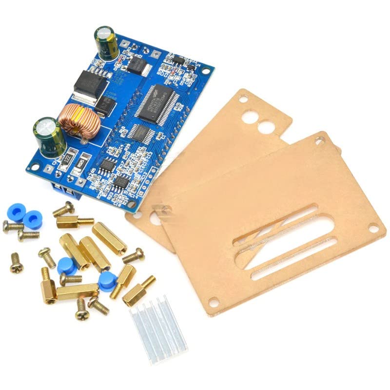
Figure 2: ZK-J5X module components before assembly.
Note: The module is a step-down converter, meaning the output voltage will always be lower than the input voltage. A minimum voltage difference of 2V is required for proper operation.
Operating Instructions and Controls
The ZK-J5X module features an LCD display and several buttons and potentiometers for control. Refer to Figure 3 for component identification.
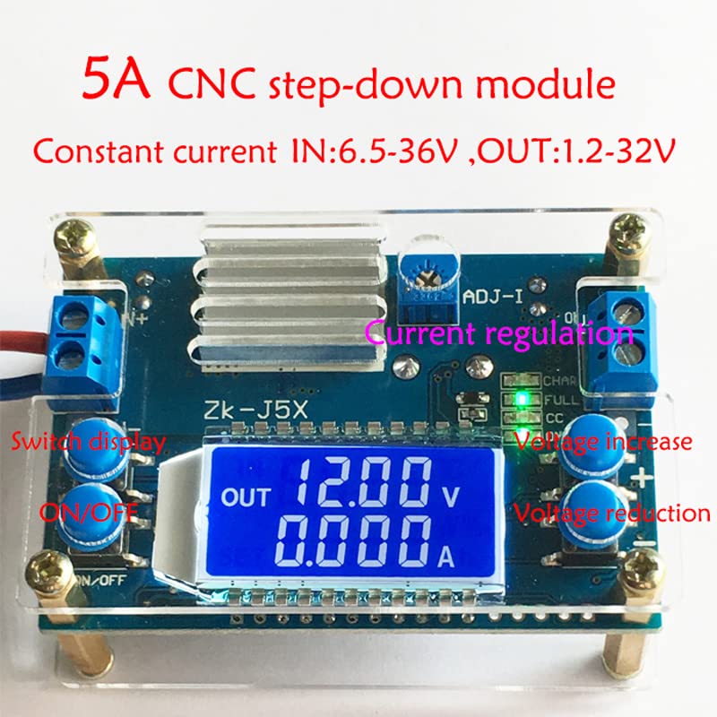
Figure 3: ZK-J5X module with labeled controls.
Control Buttons:
- ON/OFF Button: Toggles the output power on or off. When off, the display may still show input voltage, but no power is supplied to the output terminals.
- Switch Display Button: Cycles through different display modes on the LCD (e.g., Input Voltage, Output Voltage, Current, Power).
- Voltage Increase (+) Button: Increases the output voltage.
- Voltage Reduction (-) Button: Decreases the output voltage.
Potentiometers:
- ADJ-V (Voltage Adjustment Potentiometer): Fine-tunes the output voltage. Use in conjunction with the voltage increase/reduction buttons for precise setting.
- ADJ-I (Current Regulation Potentiometer): Sets the constant current limit. This is crucial when using the module as a battery charger or LED driver. Turn clockwise to increase the current limit, counter-clockwise to decrease.
Setting Output Voltage and Current:
- Setting Voltage:
- Power on the module.
- Use the Voltage Increase (+) and Voltage Reduction (-) buttons to set the desired output voltage.
- For fine adjustment, use the ADJ-V potentiometer.
- Setting Current Limit (Constant Current Mode):
- First, set the desired output voltage (e.g., for charging a 12V battery, set to 14.4V).
- Connect a multimeter in series with the output (or a known resistive load) to measure the current.
- Adjust the ADJ-I potentiometer to set the maximum desired output current. The "CC" indicator LED will illuminate when the module is operating in constant current mode.
- Important: Always set the current limit with a load connected or a multimeter in current mode. Do not short the output to set current.
Display Modes:
Press the "Switch Display" button to cycle through the following information on the LCD:
- Input Voltage (IN V)
- Output Voltage (OUT V)
- Output Current (OUT A)
- Output Power (OUT W)
- Input Voltage & Output Current (alternating)
- Output Voltage & Output Current (alternating)
- Input Voltage & Output Power (alternating)
- Output Voltage & Output Power (alternating)
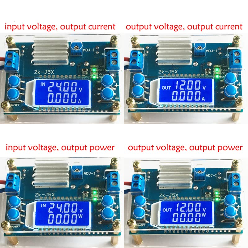
Figure 4: Examples of different display modes on the ZK-J5X LCD.
Maintenance
The REES52 ZK-J5X module is designed for reliable operation with minimal maintenance. Follow these guidelines to ensure its longevity:
- Cleaning: Keep the module clean and free from dust and debris. Use a soft, dry cloth to wipe the surfaces. Do not use liquid cleaners or solvents.
- Ventilation: Ensure proper airflow around the module, especially when operating at higher power levels. If using a fan for cooling, periodically check that the fan is clear of obstructions and functioning correctly.
- Connections: Periodically check all input and output connections to ensure they are secure and free from corrosion.
- Storage: When not in use, store the module in a dry, cool, and dust-free environment.
Troubleshooting
| Problem | Possible Cause | Solution |
|---|---|---|
| LCD display is off or abnormal. | Input voltage is too low (below 5.5V). Incorrect input polarity. No input power. | Check input power supply. Ensure input voltage is within 6.5V-36V range. Verify input polarity. |
| No output voltage. | Output is turned off (ON/OFF button). Output voltage set too low. Input voltage too low. Incorrect output polarity. Overload protection activated. | Press the ON/OFF button to enable output. Adjust output voltage using buttons/potentiometer. Check input voltage. Verify output polarity. Reduce load or check for short circuit. |
| Output voltage cannot be adjusted. | Input voltage is too close to output voltage (minimum 2V difference required). Potentiometer at its limit. | Ensure input voltage is sufficiently higher than desired output voltage. Try adjusting in the opposite direction. |
| Output current is lower than expected or fluctuates. | Current limit (ADJ-I) set too low. Load resistance too high. Overheating. | Adjust the ADJ-I potentiometer clockwise to increase the current limit. Check your load's requirements. Ensure adequate cooling. |
| Module gets excessively hot. | Operating at high power output without sufficient cooling. Ambient temperature too high. | Reduce output power or current. Ensure proper ventilation. Consider adding a cooling fan, especially for outputs above 50W or 3.5A. |
Warranty and Support
For warranty information and technical support, please refer to the retailer or manufacturer's official website where you purchased the REES52 ZK-J5X module. Keep your purchase receipt as proof of purchase.
Manufacturer: REES52
Country of Origin: China