1. Introduction
The Walfront CHLT-63 is a 3-phase DIN rail mounted device designed to monitor voltage and current, and provide automatic overvoltage and overcurrent protection for electrical systems. It features a digital display for real-time monitoring and an automatic reset function to ensure continuous operation within specified parameters. This manual provides essential information for the safe installation, operation, and maintenance of the device.
2. Safety Information
Please read and understand all safety instructions before installing or operating this device. Failure to follow these instructions may result in electric shock, fire, or serious injury.
- Installation and maintenance should only be performed by qualified electricians.
- Ensure the power supply is disconnected before any installation, wiring, or maintenance work.
- Verify that the device's voltage and current ratings match your electrical system specifications.
- Do not operate the device if it is damaged or malfunctioning.
- Avoid exposing the device to moisture, extreme temperatures, or corrosive environments.
3. Product Overview
3.1 Key Features
- Easy Installation: Designed for standard 35mm DIN rail mounting.
- Automatic Protection: Automatically cuts off power during overvoltage, undervoltage, or overcurrent conditions.
- Quick Response: Sensitive internal components ensure rapid response to electrical anomalies.
- Digital Display: Real-time display of working voltage and current for each phase (L1, L2, L3).
- Automatic Reset: Features an automatic reset function to restore power once conditions return to normal, preventing prolonged outages.
3.2 Components and Indicators

Figure 1: Front Panel Layout
This image displays the front panel of the Walfront CHLT-63 protector. It clearly shows three pairs of digital displays for Voltage (V) and Current (A) for phases L1, L2, and L3. Below the displays are four control buttons: a Manual switch (power symbol), a Menu key (M), and two Adjustment keys (up and down arrows). To the right of the buttons, various indicator symbols are labeled: Output indication, Over-voltage indication, Under-voltage indication, Over-current indication, and Voltage unbalance indication.
- Voltage Display Screen: Shows the real-time voltage for each phase (L1, L2, L3).
- Current Display Screen: Shows the real-time current for each phase (L1, L2, L3).
- Manual Switch: Power button to manually turn the device on/off.
- Menu Key (M): Used to access and navigate the device's settings menu.
- Adjustment Keys (Up/Down): Used to adjust parameter values within the settings menu.
- Output Indication (-): Indicates the output status.
- Over-voltage Indication (>U): Lights up when an overvoltage condition is detected.
- Under-voltage Indication (
- Over-current Indication (>I): Lights up when an overcurrent condition is detected.
- Voltage Unbalance Indication (Asy): Lights up when voltage unbalance is detected.
4. Specifications
| Parameter | Value |
|---|---|
| Model | CHLT-63 |
| Item Model Number | WALFRONT9kh62i4ya0-11 |
| Material | PC |
| Load Current | 1-63A |
| Overvoltage Setting Range | AC230-300V |
| Undervoltage Setting Range | AC120V-210V |
| Power Off Time (Voltage) | 1-600 seconds |
| Power Off Time (Current) | 1-600 seconds |
| Installation | Approx. 35mm DIN rail |
| Package Dimensions | 4.09 x 3.98 x 2.87 inches |
| Item Weight | 14.3 ounces |
5. Setup and Installation
The CHLT-63 protector is designed for easy installation on a standard 35mm DIN rail. Ensure all power is disconnected before proceeding with installation.
5.1 Mounting
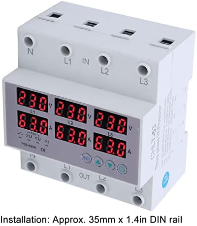
Figure 2: DIN Rail Installation
This image shows a side view of the Walfront CHLT-63 protector, highlighting its compatibility with a 35mm DIN rail. The text overlay confirms the installation method: "Installation: Approx. 35mm x 1.4in DIN rail."
- Locate a suitable 35mm DIN rail within your electrical panel.
- Align the protector's mounting clips with the DIN rail.
- Press firmly until the device clicks securely into place on the rail.
5.2 Wiring

Figure 3: Wiring Terminals
This angled view of the Walfront CHLT-63 protector clearly shows the input (IN) and output (OUT) terminals. The terminals are labeled for Neutral (N) and three phases (L1, L2, L3) at both the top (IN) and bottom (OUT) of the device, indicating where the main power supply and protected load should be connected.
- Identify the input (IN) and output (OUT) terminals on the device. The input terminals are typically at the top, labeled N, L1, L2, L3 IN. The output terminals are at the bottom, labeled N, L1, L2, L3 OUT.
- Connect the incoming 3-phase power supply (Neutral, L1, L2, L3) to the corresponding IN terminals.
- Connect the load (the circuit or equipment to be protected) to the corresponding OUT terminals.
- Ensure all connections are secure and properly tightened to prevent loose contacts and overheating.
- Double-check all wiring before restoring power.
6. Operation
6.1 Powering On and Real-time Monitoring
Once installed and wired, restore power to the circuit. The device will power on, and the digital display screens will show the real-time voltage and current for each phase (L1, L2, L3).
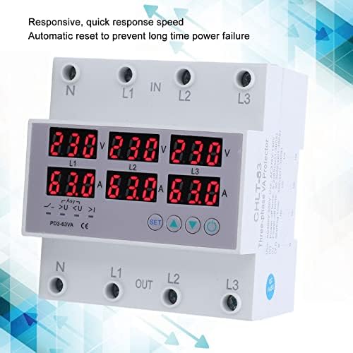
Figure 4: Real-time Display and Responsiveness
This image shows the Walfront CHLT-63 protector with its digital displays active, showing voltage and current readings for all three phases. The accompanying text highlights its "Responsive, quick response speed" and "Automatic reset to prevent long time power failure," indicating its operational efficiency.
- The top row of displays indicates voltage (V) for L1, L2, and L3.
- The bottom row of displays indicates current (A) for L1, L2, and L3.
- Observe these readings to ensure the system is operating within normal parameters.
6.2 Setting Protection Parameters
The device allows you to set specific thresholds for overvoltage, undervoltage, and power-off times. Refer to Figure 1 for button identification.
- Press the Menu key (M) to enter the settings mode.
- Use the Adjustment keys (Up/Down) to navigate through the different parameters (e.g., Overvoltage Setting Value, Undervoltage Setting, Power Off Time).
- When the desired parameter is displayed, press the Menu key (M) again to select it for editing.
- Use the Adjustment keys (Up/Down) to change the value.
- Press the Menu key (M) to confirm the new value and move to the next parameter or exit the settings.
- Overvoltage Setting Value: Adjustable from AC230-300V.
- Undervoltage Setting: Adjustable from AC120V-210V.
- Power Off Time (Voltage/Current): Adjustable from 1-600 seconds. This setting determines how long the device waits before cutting power after a fault, and how long it waits before automatically resetting after conditions normalize.
6.3 Protection Function
When the monitored voltage or current exceeds the set thresholds, the protector will automatically cut off the power supply to the load. The corresponding indicator light (e.g., >U for overvoltage) will illuminate.
After the fault condition is resolved and the system returns to normal operating parameters, the device's automatic reset function will restore power to the load after the set power-off time delay. This prevents long-term power failure and ensures system stability.
7. Maintenance
The Walfront CHLT-63 protector is designed for minimal maintenance. However, regular checks can help ensure its longevity and reliable operation.
- Periodic Inspection: Visually inspect the device and its wiring connections periodically for any signs of damage, loose connections, or discoloration.
- Cleaning: If necessary, gently clean the exterior of the device with a dry, soft cloth. Do not use abrasive cleaners or solvents. Ensure power is disconnected before cleaning.
- Environmental Conditions: Ensure the operating environment remains within the recommended temperature and humidity ranges to prevent premature failure.
8. Troubleshooting
If you encounter issues with your Walfront CHLT-63 protector, refer to the following common troubleshooting steps:
| Problem | Possible Cause | Solution |
|---|---|---|
| Device does not power on. | No power supply; incorrect wiring; device fault. | Check incoming power supply. Verify wiring connections. If power is present and wiring is correct, the device may be faulty and require replacement. |
| Power cuts off frequently. | Frequent overvoltage/undervoltage/overcurrent conditions; incorrect protection settings. | Monitor the display for fault indicators. Check the actual voltage and current of your system. Adjust protection thresholds if they are set too sensitively for your application. Investigate the cause of power fluctuations. |
| Display shows incorrect readings. | Loose wiring connections; device fault. | Ensure all wiring terminals are securely tightened. If readings remain inaccurate, the device may be faulty. |
| Device does not reset automatically. | Fault condition persists; automatic reset function disabled (if applicable); device fault. | Ensure the fault condition (overvoltage, etc.) has truly cleared. Check the power-off time setting. If the issue persists, the device may require service or replacement. |
For issues not covered here, or if troubleshooting steps do not resolve the problem, contact qualified personnel or Walfront customer support.
9. Warranty and Support
Walfront products are manufactured to high-quality standards. While specific warranty details are not provided in this manual, please retain your proof of purchase for any warranty claims. For technical support, service, or inquiries regarding your Walfront CHLT-63 protector, please refer to the contact information provided with your purchase or visit the official Walfront website.


