
1. Introduction
This manual provides essential information for the safe and efficient installation, operation, and maintenance of your U.S. Solid 3/4-inch Motorized Ball Valve. Please read these instructions thoroughly before installation and use, and retain this manual for future reference.
The U.S. Solid motorized ball valve is constructed from durable SS304 stainless steel, ensuring a lead-free and safe solution for various applications, including potable water systems. It features a full port design for optimal flow and operates on a wide voltage range of 9-24V AC/DC. The valve is designed for quick open/close cycles (3-5 seconds) and automatically ceases power consumption once fully open or closed, preventing overheating and promoting energy efficiency. An IP65 enclosure rating provides protection against dust and water jets, ensuring longevity in diverse environments. This model also includes a manual override function for operation during power outages or specific maintenance needs.
2. Safety Information
- Always disconnect power before installation, maintenance, or troubleshooting.
- Ensure proper electrical wiring according to local codes and regulations.
- Do not exceed the maximum pressure or temperature ratings specified for the valve.
- Wear appropriate personal protective equipment (PPE) during installation and maintenance.
- Avoid exposing the valve to corrosive chemicals or environments beyond its specified material compatibility.
- Ensure the valve is installed in a location where it is protected from physical damage.
3. Product Overview
The U.S. Solid motorized ball valve combines robust construction with intelligent design for reliable fluid control. Its key components include the stainless steel valve body, the electric actuator, and a manual override mechanism.
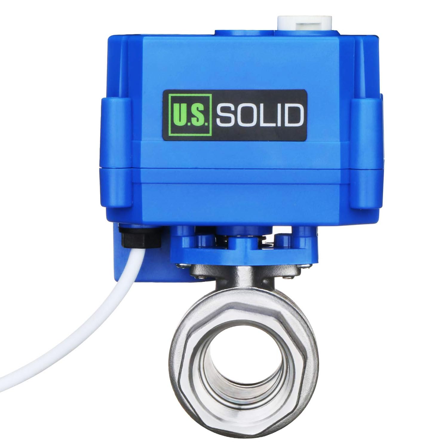
Figure 1: Front view of the U.S. Solid 3/4-inch Motorized Ball Valve.
Key Features:
- Material: SS304 Stainless Steel body and stem, PTFE ball seat, EPDM seal.
- Voltage: 9-24V AC/DC wide operating voltage range.
- Operation: Full port design for unrestricted flow; 3-5 second open/close time.
- Energy Efficiency: Power consumption ceases once the valve reaches its fully open or closed position.
- Protection: IP65 rated enclosure for dust and water jet resistance.
- Manual Override: Allows for manual operation of the valve.
- Position Indicator: Visual indicator on the actuator shows the current valve position (open/closed).

Figure 2: Close-up of the manual override knob and position indicator.
4. Specifications
| Parameter | Value |
|---|---|
| Model Number | USS-MSV00203 |
| Valve Material | SS304 Stainless Steel |
| Ball Seat Material | PTFE |
| Seal Material | EPDM |
| Thread Size | 3/4 inch BSPP (G) |
| Bore Type | Full Port |
| Operating Voltage | 9-24V AC/DC |
| Max Power Consumption | 2 W |
| Max Torque | 2 N·m |
| Open/Close Time | 3-5 seconds |
| Max Working Pressure | 1.0 MPa (145 PSI) |
| Flow Medium Temperature | 0°C to 90°C (32°F to 194°F) |
| Ambient Temperature | -10°C to 40°C (14°F to 104°F) |
| Enclosure Rating | IP65 |
| Life Expectancy | 80,000-100,000 cycles |
| Dimensions (LxWxH) | 9 x 9.2 x 12.1 cm (3.54 x 3.62 x 4.76 inches) |
| Weight | 1 lb (0.45 kg) |

Figure 3: Top view of the valve actuator showing key specifications.
5. Setup and Installation
Proper installation is crucial for the valve's performance and longevity. Follow these general guidelines:
- Preparation: Ensure the pipeline is clean and free of debris before installation. Verify that the valve's specifications (size, pressure, temperature) match your application requirements.
- Mounting: Install the valve in the desired position, ensuring the flow direction matches the application. The valve can be installed in any orientation, but ensure adequate space for wiring and manual override access.
- Threading: Apply appropriate thread sealant (e.g., PTFE tape) to the pipe threads. Carefully thread the valve onto the pipes, ensuring a tight, leak-free connection. Do not overtighten, as this can damage the valve body or threads.
- Wiring: This valve uses a 3-wire positive break configuration. Connect the power supply (9-24V AC/DC) to the appropriate terminals on the actuator. Refer to the wiring diagram (if provided with the product packaging) for specific connections. Ensure all electrical connections are secure and insulated.
- Testing: After installation and wiring, slowly introduce fluid into the system and check for leaks. Then, apply power and test the motorized operation.
6. Operating Instructions
Motorized Operation:
The valve operates by applying power to the actuator. Depending on the wiring configuration, applying power will either open or close the valve. The actuator will automatically stop once the valve reaches its fully open or closed position.
- To open the valve: Apply power to the designated 'open' wire.
- To close the valve: Apply power to the designated 'close' wire.
- The position indicator on top of the actuator provides a visual confirmation of the valve's current state.
Manual Override Function:
This valve is equipped with a manual override feature, allowing you to operate it without electrical power or to adjust it if the valve is stuck.
- To engage manual override: Locate the manual override knob on the side of the actuator (refer to Figure 2).
- Operation: Turn the knob to manually open or close the valve. The position indicator will move accordingly.
- Disengagement: Once manual adjustment is complete, ensure the knob is returned to its neutral position to allow for motorized operation.
7. Maintenance
The U.S. Solid motorized ball valve is designed for minimal maintenance. However, periodic checks can ensure optimal performance and extend its lifespan.
- Regular Inspection: Periodically inspect the valve for any signs of leaks, corrosion, or physical damage.
- Cleaning: Keep the exterior of the actuator clean and free from excessive dust or debris. Do not use harsh chemicals that could damage the IP65 enclosure.
- Electrical Connections: Ensure all electrical connections remain secure and free from corrosion.
- Actuator Function: Occasionally cycle the valve through its full open and close positions to ensure smooth operation.
- Seal Replacement: If leaks occur around the stem or ball, the seals (PTFE ball seat, EPDM gasket) may need replacement by a qualified technician.
8. Troubleshooting
| Problem | Possible Cause | Solution |
|---|---|---|
| Valve does not operate when power is applied. | No power supply; incorrect wiring; actuator fault. | Check power supply and connections. Verify wiring against diagram. If problem persists, contact support. |
| Valve leaks from connections. | Improperly sealed threads; damaged threads. | Ensure proper thread sealant application. Retighten connections carefully. Inspect threads for damage. |
| Valve leaks from body/stem. | Damaged seals (ball seat, stem seal). | Contact a qualified technician for seal inspection and replacement. |
| Valve operates slowly or gets stuck. | Debris in valve; low voltage; mechanical obstruction. | Check power supply voltage. Use manual override to free the valve. Flush the system to remove debris. |
| Manual override knob is stiff or non-functional. | Internal mechanism obstruction; damage to knob. | Do not force the knob. Inspect for visible obstructions. If damaged, contact support. |
9. Warranty and Support
For warranty information, technical support, or service inquiries, please contact U.S. Solid customer service. Keep your purchase receipt and model number (USS-MSV00203) handy when contacting support.
Contact information can typically be found on the U.S. Solid official website or through your point of purchase.