1. Product Overview
This U.S. Solid 1-inch G-threaded motorized ball valve, constructed from SS304 stainless steel, is designed for reliable fluid control in various applications. It operates on 9-24V AC/DC power, opening or closing in 3-5 seconds, and features an automatic power cut-off to prevent overheating. The valve is lead-free, suitable for potable water, and boasts an IP65 rated housing for dust and water jet protection. It includes a manual override function and a position indicator for convenience. This valve is ideal for domestic water systems, home automation, brewing, and Arduino projects.
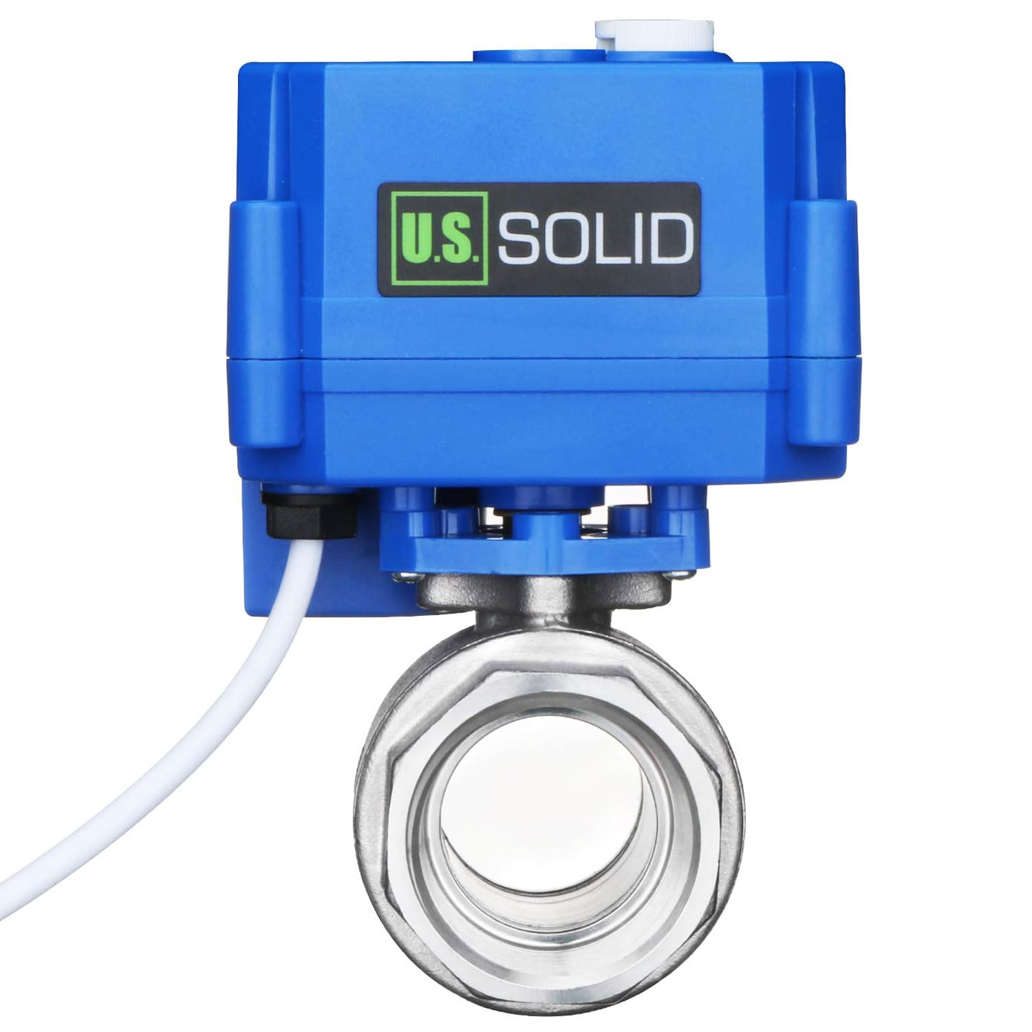
Figure 1: Front view of the U.S. Solid 1-inch Motorized Ball Valve.
2. Safety Information
- Always disconnect power before installation, maintenance, or troubleshooting.
- Ensure the operating voltage (9-24V AC/DC) matches your power supply.
- Do not exceed the maximum pressure rating of 1.0 MPa.
- Install the valve in an environment within the specified ambient temperature range (-10 °C to 40 °C).
- Ensure proper grounding to prevent electrical hazards.
- Consult a qualified professional for installation if you are unsure.
3. Package Contents
Verify that all items are present upon unpacking:
- U.S. Solid Motorized Ball Valve (USS-MSV102F6C)
- User Manual (this document)
4. Technical Specifications
| Feature | Specification |
|---|---|
| Model Number | USS-MSV102F6C |
| Valve Material | SS304 Stainless Steel |
| Ball Seat | PTFE |
| Seal Material | EPDM |
| Open/Close Time | 3-5 seconds |
| Operating Voltage | 9-24V AC/DC |
| Max Power Consumption | 2 W |
| Max Torque | 2 N·m |
| Max Pressure | 1.0 MPa (1000 kPa) |
| Medium Temperature Range | 0 °C to 90 °C |
| Ambient Temperature Range | -10 °C to 40 °C |
| IP Rating | IP65 |
| Life Cycle | 80,000 to 100,000 cycles |
| Bore Type | Full Port |
| Thread Type | BSPP (G) - British Standard Parallel Pipe |
| Product Dimensions (L x W x H) | 8.99 x 10.21 x 11.1 cm |
| GTIN/UPC | 888107104278 |

Figure 2: Product label with key specifications.

Figure 3: Technical drawing with dimensions for various valve sizes.
5. Installation
5.1. Mounting the Valve
- Ensure the pipeline is clean and free of debris before installation.
- Apply appropriate thread sealant to the valve threads.
- Thread the valve into the pipeline, ensuring a tight, leak-free connection. Do not overtighten.
- Orient the valve so the actuator is easily accessible for wiring and manual override.

Figure 4: Close-up of the valve's threaded connection.
5.2. Electrical Connection
The valve operates on 9-24V AC/DC. This model features a 3-wire positive break configuration. Refer to the wiring diagram provided with your specific product or consult the manufacturer's website for detailed instructions if the included diagram is unclear.
- Red Wire: Connect to positive (+) power supply.
- Black Wire: Connect to negative (-) power supply.
- Yellow Wire: Control wire for valve position.
Typically, applying voltage between Red and Black wires powers the actuator. The Yellow wire, when energized, controls the valve's open/close state. Ensure all connections are secure and insulated.
6. Operation
6.1. Automatic Operation
Once properly installed and wired, the valve will open or close automatically when power is applied to the control circuit. The valve will consume power only during the opening or closing cycle (3-5 seconds) and then automatically cut off power, preventing overheating.
- To Open: Apply power to the designated control wire (e.g., Yellow wire). The valve will rotate to the open position.
- To Close: Reverse the polarity or switch the control signal as per your wiring configuration. The valve will rotate to the closed position.
The position indicator on top of the actuator provides a visual confirmation of the valve's current open or closed state.
6.2. Manual Override Function
This valve is equipped with a manual override function, allowing you to operate it manually in case of power failure or if the valve becomes stuck.
- Locate the manual override knob on the actuator (refer to Figure 5).
- Turn the knob clockwise or counter-clockwise to manually open or close the valve.
- Ensure the valve is fully open or closed as required.

Figure 5: Manual override knob on the actuator.
7. Maintenance
The U.S. Solid motorized ball valve is designed for minimal maintenance. However, regular checks can ensure optimal performance and longevity.
- Periodic Inspection: Regularly inspect the valve and connections for any signs of leaks, corrosion, or damage.
- Cleaning: Keep the exterior of the actuator clean and free from excessive dust or moisture. The IP65 rating protects against dust and water jets, but extreme conditions should be avoided.
- Functionality Check: Periodically test the automatic and manual operation of the valve to ensure it opens and closes smoothly.
- Avoid Harsh Chemicals: Do not use abrasive cleaners or harsh chemicals on the valve body or actuator, as this may damage the materials or seals.
8. Troubleshooting
If you encounter issues with your motorized ball valve, refer to the table below for common problems and solutions.
| Problem | Possible Cause | Solution |
|---|---|---|
| Valve does not open/close automatically. | No power, incorrect wiring, power supply outside 9-24V AC/DC range, motor fault. | Check power supply. Verify wiring connections against the diagram. Ensure voltage is within range. If issues persist, contact support. |
| Valve is stuck or operates slowly. | Debris in the valve, low power, mechanical obstruction. | Use the manual override to check for mechanical issues. Flush the system if debris is suspected. Verify power supply. |
| Leakage from connections. | Improperly tightened connections, damaged threads, insufficient thread sealant. | Disconnect power, drain system. Re-tighten connections with proper thread sealant. Inspect threads for damage. |
| Actuator makes noise but valve doesn't move. | Motor gear issue, valve seized. | Attempt manual override. If the valve moves manually, the motor may be faulty. If it doesn't move manually, the valve itself may be seized. Contact support. |
Note: A user review mentioned that the provided wiring schematic might be generic and not specific to the manual function model. If you encounter wiring difficulties, search for the specific wiring diagram for the USS-MSV102F6C model with 3-wire positive break and manual function.
9. Warranty Information
U.S. Solid products are manufactured to high-quality standards. For specific warranty terms and conditions, please refer to the warranty card included with your product or visit the official U.S. Solid website. Keep your purchase receipt as proof of purchase for any warranty claims.
10. Customer Support
For technical assistance, troubleshooting beyond this manual, or inquiries about your U.S. Solid motorized ball valve, please contact U.S. Solid customer support through their official website or the contact information provided with your purchase. When contacting support, please have your model number (USS-MSV102F6C) and purchase details ready.