1. Introduction
This manual provides comprehensive instructions for the installation, operation, and maintenance of your MOES BAT-80A Smart Automatic Transfer Switch. This device is designed to manage power flow between DC input sources (inverter) and AC input sources (public power/grid) in off-grid solar and wind systems, ensuring continuous power supply and optimizing energy usage.
2. Safety Information
- Installation must be performed by qualified personnel in accordance with local electrical codes.
- Ensure all power sources are disconnected before installation or maintenance to prevent electric shock.
- Verify correct wiring polarity for battery connections.
- Do not operate the device if it appears damaged.
- The device is designed for specific voltage and current ratings (80A, 8KW/100-120V, 16KW/220-240V). Exceeding these limits can cause damage or hazards.
- This device includes surge protection; however, additional external surge protection may be required depending on your system.
3. Product Overview
3.1 Key Features
- Automatic power switching between inverter (DC input) and public power (AC input).
- Supports off-grid solar and wind systems.
- Manual source switching capability.
- Integrated Battery Management System (BMS) for monitoring grid, battery, and inverter voltage, current, power, and electricity consumption.
- Fast switching times: Inverter to public power ≤10ms, public power to inverter ≤16ms.
- Surge protection for enhanced circuit safety.
- Large LCD display for real-time status monitoring.
- Auto-distinguishes DC 12/24/48V and AC 100-120V 60HZ / 220-240V 50HZ.
- Adjustable battery low voltage transfer (cut-off) and recovery set-points.
- MOES App Bluetooth control (requires MOES Bluetooth hub for remote control outside Bluetooth range).
3.2 Components
The MOES BAT-80A Smart Automatic Transfer Switch includes the main transfer switch unit and a MOES Bluetooth hub for extended remote control capabilities.
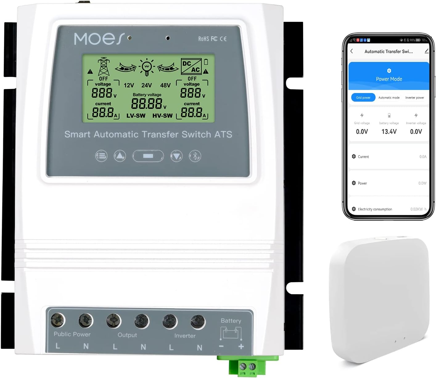
Figure 1: MOES BAT-80A Smart Automatic Transfer Switch and Bluetooth Hub. The image shows the main white transfer switch unit with an LCD display, alongside a smartphone displaying the MOES app interface and a small white Bluetooth hub.
4. Specifications
| Parameter | Value |
|---|---|
| Model | BAT-80A |
| Rated Power | 8KW (Utility Power 100-120V); 16KW (Utility Power 220-240V) |
| Input Voltage | Auto Selection: AC 100-120V or AC 220-240V |
| Output Voltage | Auto Selection: AC 100-120V or AC 220-240V |
| Transfer Time (Inverter to Utility) | ≤10ms |
| Transfer Time (Utility to Inverter) | ≤16ms |
| LCD Display | Battery voltage; Power source: Utility power or battery-inverter. |
| System Voltage | Auto Select: 12V or 24V or 48V |
| Battery Low Voltage Transfer Setpoints (Default) | 10.5V/21V/42V, adjustable |
| Battery Recovery Setpoints (Default) | 12.5V/25V/50V, adjustable |
| Application | Off-grid solar system; Wind generator; Hydro generator |
| Product Size | 7.48"L x 6.69"W x 2.8"H (190mm x 169.5mm x 72.5mm) |
| Item Weight | 3.5 Pounds (1.32KG) |
| Material | Polycarbonate (PC) |

Figure 2: Detailed dimensions and wire gauge information for the MOES BAT-80A Smart Automatic Transfer Switch. Maximum wire gauge: AWG 14 (2.5mm²) for Public Power, Output, Inverter; AWG 6 (16mm²) for Battery.
5. Setup and Installation
Proper installation is crucial for the safe and efficient operation of your automatic transfer switch. Please follow these steps carefully.
5.1 Wiring Diagram
Refer to the wiring diagram below for connecting the public power, inverter, battery, and load to the transfer switch.

Figure 3: Product Wiring Diagram. This diagram illustrates the connections for a typical off-grid system, showing the solar panel, wind generator, solar charge controller, battery, inverter, MOES transfer switch, grid connection, and household load.
Important: Ensure that the neutral (N) and live (L) lines are correctly identified and connected for all AC inputs and outputs. The battery terminals are clearly marked positive (+) and negative (-).
5.2 Installation Video Guide
Video 1: Automatic Transfer Switch Installation. This video demonstrates the physical wiring process for the automatic transfer switch, connecting the various power sources and loads.
6. Operating Instructions
The MOES BAT-80A offers both automatic and manual operation modes, along with smart control via the MOES App.
6.1 Automatic Switching Logic
- Inverter Priority: The system prioritizes power from the inverter (derived from solar/wind energy).
- Automatic Transfer to Grid: If the battery voltage drops below the user-defined "cut-off" point (e.g., due to insufficient solar/wind energy), the switch will automatically transfer the load to public power (grid) to protect the battery.
- Automatic Transfer to Inverter: When the battery voltage recovers and rises above the user-defined "recovery" point, the switch will automatically transfer the load back to the inverter.

Figure 4: Product Function Diagram. This diagram illustrates the automatic power switching logic between grid power and battery/inverter power based on battery charge levels.

Figure 5: Fast Switching Speed. This image highlights the rapid transfer times (≤10ms from inverter to public power, ≤16ms from public power to inverter) ensuring uninterrupted operation of connected devices.
6.2 Manual Switching
The device supports manual switching between power sources. Consult the device's physical controls for manual override options.
6.3 MOES App Control
The MOES BAT-80A can be monitored and controlled via the MOES App. A Bluetooth hub (included) is required for remote control beyond Bluetooth range.

Figure 6: MOES App Control Interface. This image displays the smartphone app interface for monitoring and controlling the transfer switch, showing current power status and settings.
Video 2: How to Use the Automatic Transfer Switch. This video provides a demonstration of the automatic transfer switch in operation, including its display and switching behavior.
6.4 Adjustable Set-points
You can customize the battery low voltage transfer (cut-off) and recovery voltage set-points directly on the device or via the MOES App. Ensure the recovery voltage is always set higher than the cut-off voltage. These settings are compatible with various battery types including Sealed, Gel, Lead-acid, and Lithium batteries, provided the voltage is within the device's operating range.
7. Maintenance
- Regularly inspect all wiring connections for tightness and signs of wear or corrosion.
- Keep the device clean and free from dust and debris. Use a dry, soft cloth for cleaning.
- Periodically check the LCD display for any error messages or unusual readings.
- Ensure adequate ventilation around the device to prevent overheating.
8. Troubleshooting
| Problem | Possible Cause | Solution |
|---|---|---|
| Device not powering on | No input power; loose connections. | Check public power and inverter connections. Ensure battery is connected and charged. Verify all wiring is secure. |
| No automatic switching | Incorrect set-points; battery voltage not reaching thresholds; device in manual mode. | Verify battery cut-off and recovery voltage settings. Check battery charge level. Ensure device is in automatic mode. |
| Load not receiving power | Input power failure; output wiring issue; device fault. | Check both public power and inverter status. Inspect load wiring. If issues persist, contact support. |
| App connection issues | Bluetooth not enabled; hub not connected/powered; device out of range. | Ensure Bluetooth is active on your smartphone. Verify the Bluetooth hub is powered and within range. Re-pair the device if necessary. |
9. Warranty and Support
MOES products are designed for reliability and performance. For warranty information, technical support, or service inquiries, please refer to the contact details provided with your purchase or visit the official MOES website. Keep your purchase receipt as proof of purchase for warranty claims.


