1. Introduction
This manual provides comprehensive instructions for the installation, operation, and maintenance of the LCLCTC Din Rail Solid State Relay with Heat Sink, Model LCDS4048ZD3. This 40A DC to AC relay is designed for efficient and reliable control in various industrial and scientific applications. Please read this manual thoroughly before installation and operation to ensure proper functionality and safety.

Figure 1: LCLCTC Din Rail Solid State Relay with integrated heat sink.
2. Product Features
- Integrated Heat Sink: Comes with its own heat sink, eliminating the need for additional purchases.
- Din Rail Mounting: Features mounting rail clips suitable for easy installation in distribution boxes.
- Compact Design: With a width of only 0.964 inches (2.45 cm), it is ideal for installations in narrow spaces.
- Optimized Heat Dissipation: Designed with dual-sided heat dissipation. For optimal performance when multiple units are installed side-by-side, it is recommended to use corresponding fans to prevent compromised heat dissipation efficiency.
- Reliability: Solid state design offers longer lifespan and more stable output compared to mechanical relays.
3. Setup and Installation
Proper installation is crucial for the safe and effective operation of the solid state relay. Follow these steps carefully:
3.1. Mounting the Relay
The relay is designed for DIN rail mounting. Simply align the clips on the back of the relay with the DIN rail and press firmly until it clicks into place. Ensure the relay is securely fastened to prevent movement during operation.

Figure 2: Securely mounting the solid state relay onto a DIN rail.

Figure 3: Illustration of heat dissipation considerations when installing multiple relays side-by-side. Adequate spacing or additional cooling (fans) may be required.
3.2. Wiring Diagram (DC to AC)
Connect the input and output terminals as shown in the diagram below. Ensure all connections are tight and secure to prevent loose contacts and potential hazards. The input control voltage is 3-32V DC, and the output load voltage is 24-480V AC.

Figure 4: Detailed wiring diagram for the DC to AC solid state relay. Terminals 1 and 2 are for AC output (load), and terminals 3 and 4 are for DC input (control).
Note: In the off state, if the off-state leakage current is less than 5mA, this scenario is not applicable. Please purchase with caution.
3.3. Choosing the Correct Current Rating
It is essential to select the appropriate current rating for your application to ensure the longevity and safe operation of the SSR. Use the following guidelines:
- For resistive loads (e.g., heating equipment): SSR current = 2 x operating current of the load.
- For inductive loads (e.g., motors): SSR current = 6 x operating current of the load.
- For capacitive loads (e.g., capacitance): SSR current = 10 x operating current of the load.
Example: If you have a water pump (inductive load) rated at 2200W, 220V, the rated current is 10A. For an inductive load, you would need a 10A x 6 = 60A SSR. This product is 40A, so it would not be suitable for this specific example.

Figure 5: Table illustrating voltage control ranges for different SSR types (DC-AC, AC-AC, DC-DC) and guidelines for selecting the correct current based on load type.
3.4. Installation Video Guide
For a visual guide on how to install a solid state relay, please watch the official video below:
Video 1: "How to Install a Solid State Relay" by Leichi. This video demonstrates the physical installation process of the solid state relay on a DIN rail and basic wiring steps.
4. Operation
Once properly installed and wired, the solid state relay operates by receiving a low-voltage DC control signal (3-32V DC) at its input terminals (3 and 4) to switch a higher-voltage AC load (24-480V AC) connected to its output terminals (1 and 2). When the control signal is applied, the internal semiconductor switch closes, allowing current to flow to the load. When the control signal is removed, the switch opens, interrupting the current flow.
Always ensure that the load current does not exceed the relay's rated capacity (40A) and consider the derating factors for inductive and capacitive loads as outlined in Section 3.3.
5. Maintenance
Solid state relays are generally low-maintenance devices due to their lack of moving parts. However, regular checks can ensure optimal performance and longevity:
- Temperature Monitoring: Periodically check the temperature of the heat sink during operation. Excessive heat can indicate an overloaded condition or insufficient ventilation.
- Ventilation: Ensure adequate airflow around the relay, especially if multiple units are installed in close proximity. Consider adding a fan if heat buildup is observed (refer to Figure 3).
- Connection Integrity: Verify that all wiring connections remain tight and free from corrosion. Loose connections can lead to overheating and unreliable operation.
- Cleanliness: Keep the relay and its surroundings free from dust and debris, which can impede heat dissipation.
6. Troubleshooting
If you encounter issues with your solid state relay, consider the following common problems and solutions:
| Problem | Possible Cause | Solution |
|---|---|---|
| Relay does not switch ON/OFF |
|
|
| Relay overheats |
|
|
| Unexpected behavior / Malfunction |
|
|
Important: You should test the product under load to ensure it's functioning properly before full deployment.
7. Specifications
| Feature | Detail |
|---|---|
| Product Dimensions | 3.25 x 0.96 x 3.48 inches; 7.02 ounces |
| Date First Available | December 14, 2022 |
| Manufacturer | LCTC |
| ASIN | B0BQ2RFW6G |
| Connector Type | Quick Connect |
| Contact Material | Copper |
| Contact Type | Normally Open |
| Current Rating | 40 Amps |
| Mounting Type | DIN Rail Mount |

Figure 6: Product dimensions and packaging details.
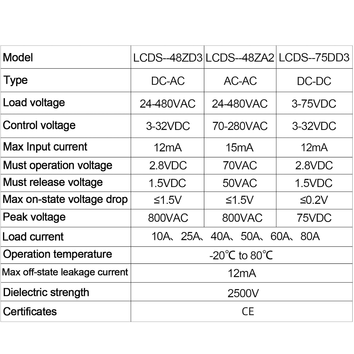
Figure 7: Comprehensive table of technical specifications for various LCLCTC solid state relay models, including load voltage, control voltage, current, and operating temperature.
8. What's in the Box
- 1 x LCLCTC Din Rail Solid State Relay (Model: LCDS4048ZD3)
9. Warranty and Support
Specific warranty details are not provided in the product information. For warranty claims, technical support, or any inquiries regarding the LCLCTC Din Rail Solid State Relay, please contact the manufacturer or the seller directly through your purchase platform.
It is recommended to retain your proof of purchase for any support requests.
