ATO ATO 5 hp 3.7 kW
ATO 5 hp 3.7 kW 460V Three-Phase Variable Frequency Drive (VFD) User Manual
Model: ATO 5 hp 3.7 kW
1. Introduction
This manual provides essential information for the safe and efficient operation of your ATO 5 hp 3.7 kW 460V Three-Phase Variable Frequency Drive (VFD). Please read this manual thoroughly before installation, operation, or maintenance to ensure proper usage and prevent potential hazards.
2. Safety Information
WARNING: Risk of electric shock.
- Read the manual and follow all safety instructions before operation.
- Do not remove the cover while power is applied.
- Wait for at least 10 minutes after disconnecting power supply to open the cover. This allows residual voltage to dissipate.
- Do not connect power to output terminals.
- The inverter must be securely grounded (earth).
- Only qualified personnel should perform installation and maintenance.
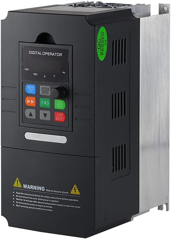
Figure 1: Angled view of the ATO VFD, highlighting the control panel and safety warning label.
3. Product Overview
The ATO 5 hp 3.7 kW Three-Phase VFD is designed for precise speed control of three-phase induction motors. It features adjustable output frequency, automatic energy-saving operation, automatic voltage regulation, and current limiting to prevent frequent over-current trips.

Figure 2: Front view of the ATO VFD, showing the digital operator panel with buttons and display.
4. Specifications
| Parameter | Value |
|---|---|
| Model Name | 5 hp 3.7 kW Three Phase VFD Inverter |
| Input Voltage | 3 phase 460V AC ±15% (Optional: 220V/480V) |
| Input Frequency | 50Hz/60Hz |
| Output Power | 3.7kW/4kW (5 hp) |
| Output Voltage | 3 phase AC 0~input voltage |
| Output Frequency | 0.00~400.00Hz |
| Item Weight | 6.6 pounds |
| Package Dimensions | 11.4 x 9 x 7 inches |
| Recommended Uses | Fans, power tools, pumps, workshop equipment |
5. Setup and Installation
Proper installation is crucial for the VFD's performance and safety. Consult a qualified electrician for wiring if you are unfamiliar with industrial electrical systems.
5.1 Wiring Connections
Connect the three-phase input power to the designated input terminals (R, S, T) and the motor to the output terminals (U, V, W). Ensure proper grounding of the VFD chassis.
- Input Power: Connect 3-phase 460V AC to the input terminals.
- Motor Connection: Connect your 3-phase induction motor to the output terminals.
- Grounding: Ensure the VFD is properly grounded to prevent electrical hazards.
5.2 Motor Compatibility
When selecting a VFD, ensure:
- The rated current of the VFD is greater than the rated current of your motor.
- The rated power of the VFD is greater than the rated power of your motor, preferably by at least one level.
If unsure, provide your motor nameplate photo, input power supply details, and requirements to customer support for assistance.
6. Operating Instructions
The VFD supports various control methods and programmable parameters.
6.1 Basic Operation
The digital operator panel allows for direct control and parameter adjustment.
- MENU/ESC: Access menu or exit current setting.
- ENTER/DATA: Confirm selection or enter data.
- FWD/REV: Control forward/reverse direction.
- UP/DOWN Arrows: Adjust frequency or navigate parameters.
- JOG/REV: Jog operation or reverse direction.
- STOP/RESET: Stop operation or reset errors.
6.2 Frequency Control Methods
The VFD offers several methods to control motor frequency:
- Switch Button Control: Use external switch signals to start/stop the VFD and activate multi-speed settings.
- Analog Control: Control frequency using a 5V or 0-20mA analog signal, in conjunction with switch control for start/stop.
- Potentiometer Control: Direct frequency control using the VFD's built-in potentiometer input terminal.
- Modbus-RTU Control: Utilize the RS485 interface for data transmission with Modbus-RTU protocol to monitor, modify frequency, start, and stop the VFD.
- DTU Wireless Remote Control: Combine a DTU terminal with the VFD for wireless transmission, where the DTU outputs an analog quantity to control VFD frequency.
6.3 Programming Parameters
The VFD supports customization of various parameters, including acceleration/deceleration time, frequency settings, and motor protection. Refer to the detailed programming guide (if provided separately) for specific parameter codes and values.
7. Maintenance
Regular maintenance ensures the longevity and optimal performance of your VFD.
- Keep the VFD clean and free from dust and debris.
- Ensure adequate ventilation around the unit to prevent overheating.
- Periodically check all wiring connections for tightness and signs of wear.
- Inspect cooling fans for proper operation and clear any obstructions.
8. Troubleshooting
8.1 Common Issues and Solutions
- Incorrect Output Voltage (e.g., 380V instead of 460V): If the factory default output voltage is incorrect, adjust parameter P0.08 to the desired voltage (e.g., P0.08 = 460V).
- VFD Not Responding: Check power connections, input voltage, and ensure no error codes are displayed.
- Motor Not Running: Verify motor wiring, VFD output frequency, and motor parameters.
8.2 Factory Reset
To restore the VFD to factory settings, set parameter Pd.01 = 1.
9. Customer Support
If you have any questions, encounter issues with the product, or require technical assistance, please do not hesitate to contact ATO customer support. Our professional technicians are available to help you.
We aim to respond to all inquiries within 12 hours.
Ask a question about this manual
Ask about setup, troubleshooting, compatibility, parts, safety, or missing instructions. Manuals+ will review the question and use this page’s manual context to help answer it.