1. Introduction
The LILYGO T-CAN485 is an ESP32-based development board designed for wireless IoT control applications, featuring integrated CAN bus and RS485 interfaces. This board supports TF card storage and offers Wi-Fi and Bluetooth connectivity, making it suitable for a wide range of industrial and hobbyist projects requiring robust communication and processing capabilities.
2. Product Overview
The LILYGO T-CAN485 board integrates an ESP32 microcontroller with various communication interfaces and features. Understanding the layout and components is crucial for proper use.
2.1 Board Components
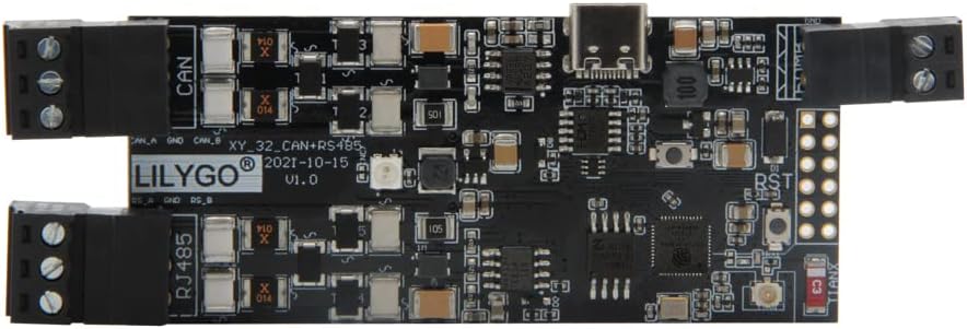
Figure 2.1: Top view of the LILYGO T-CAN485 ESP32 Development Board. This image highlights the main components including the ESP32 module, USB-C port, and terminal blocks for CAN and RS485 connections.

Figure 2.2: Bottom view of the LILYGO T-CAN485 ESP32 Development Board, showing the integrated TF card slot for data storage.

Figure 2.3: Detailed pinout diagram for the LILYGO T-CAN485 board, indicating GPIO assignments for CAN, RS485, SD card, and other peripherals.
2.2 Product Application Instructions Video
Video 2.1: This video provides a visual guide to the application and features of the LILYGO T-CAN485 board, demonstrating its capabilities in a practical context.
3. Setup
3.1 Power Supply
The LILYGO T-CAN485 board can be powered via the USB-C port or through the DC 5-12V input. Ensure the power supply meets the specified voltage range to prevent damage to the board.
- USB-C Power: Connect a standard USB-C cable to the board's USB-C port and to a computer or a 5V USB power adapter.
- DC Power: Connect a 5-12V DC power source to the designated power input terminals. Observe correct polarity.
3.2 Driver Installation
The board uses the CH9102 USB to TTL chip. Drivers may be required for your operating system (Windows, macOS, Linux) to recognize the board. Typically, these drivers are automatically installed or can be found on the CH9102 manufacturer's website.
3.3 Development Environment Setup
To program the ESP32, you will need to set up a development environment. The Arduino IDE with ESP32 board support is a common choice. Follow these general steps:
- Install the Arduino IDE.
- Add the ESP32 board manager URL to Arduino IDE preferences.
- Install the ESP32 boards package from the Board Manager.
- Select the appropriate ESP32 board model (e.g., ESP32 Dev Module) and COM port in the Arduino IDE Tools menu.
4. Operating Instructions
4.1 Basic Programming
Once your development environment is set up, you can upload sketches (programs) to the ESP32. Connect the board via USB-C, select the correct board and port, then upload your code.
4.2 CAN Bus Communication
The T-CAN485 board includes a CAN bus interface. Refer to the pinout diagram (Figure 2.3) for CAN TX (GPIO27), CAN RX (GPIO26), and SE (GPIO23) connections. Libraries for ESP32 CAN communication are available and can be integrated into your Arduino sketches.
4.3 RS485 Communication
The board also features an RS485 interface. The RS485 TX (GPIO22), RX (GPIO21), SE (GPIO19), and EN (GPIO17) pins are available via the terminal blocks. Utilize appropriate RS485 libraries for ESP32 to manage data transmission and reception.
4.4 TF Card Usage
The integrated TF card slot allows for data logging or storing configuration files. Standard SD card libraries for ESP32 can be used to interact with the TF card. Ensure the card is properly formatted (e.g., FAT32) before use.
4.5 Wireless Connectivity (Wi-Fi & Bluetooth)
Leverage the ESP32's built-in Wi-Fi (802.11 b/g/n) and Bluetooth (BRV4.2+BLE) capabilities for network connectivity and device pairing. Standard ESP-IDF or Arduino ESP32 libraries provide functions for managing Wi-Fi connections, setting up access points, and handling Bluetooth communications.
5. Maintenance
To ensure the longevity and optimal performance of your LILYGO T-CAN485 board, follow these maintenance guidelines:
- Keep Dry: Avoid exposure to moisture or high humidity, which can damage electronic components.
- Cleanliness: Periodically clean the board with a soft, dry brush to remove dust and debris. Do not use liquid cleaners.
- Temperature: Operate the board within its specified temperature range. Extreme temperatures can affect performance and lifespan.
- Firmware Updates: Regularly check the official LILYGO GitHub repository (github.com/Xinyuan-LilyGO/T-CAN485) for firmware updates and bug fixes.
6. Troubleshooting
If you encounter issues with your LILYGO T-CAN485 board, consider the following troubleshooting steps:
- Board Not Detected: Ensure USB drivers (CH9102) are correctly installed. Try a different USB cable or port.
- Upload Errors: Verify that the correct ESP32 board and COM port are selected in your IDE. Check for syntax errors in your code. Ensure the board is in programming mode (sometimes requires holding the BOOT button while pressing RST).
- CAN Bus Issues: Confirm correct wiring of CAN H and CAN L. Check for proper termination resistors in the CAN network. Depending on the ESP32 chip version, the CAN controller register IER parameter might need adjustment (e.g., 0xEF for V3, 0xFF otherwise).
- RS485 Communication Failure: Verify RS485 A/B line connections and ensure the transceiver enable pin (EN) is correctly controlled.
- Wi-Fi/Bluetooth Connectivity Problems: Check network credentials. Ensure antennas are properly connected if external ones are used. Verify power supply stability.
7. Specifications
| Feature | Specification |
|---|---|
| Microcontroller | ESP32 |
| USB to TTL Chip | CH9102 |
| Power Input | DC 5~12V (USB-C also for 5V) |
| Bus Interfaces | UART, SPI, I2C, CAN, I2S, SDIO |
| Wireless Connectivity | Wi-Fi: 802.11 b/g/n, BRV4.2+BLE |
| Onboard Buttons | RST, BOOT |
| RGB LED | WS2812 RGB (GPIO04) |
| Storage | TF Card Support |
| Dimensions | Approximately 4.21 x 1.38 x 0.43 inches |
| Operating System Compatibility | Windows, macOS, Linux |
8. Support & Warranty
For technical support, documentation, and community resources, please visit the official LILYGO GitHub page:
LILYGO products typically come with a standard manufacturer's warranty covering defects in materials and workmanship. For specific warranty terms and conditions, please refer to the purchase documentation or contact LILYGO customer service directly. Keep your proof of purchase for warranty claims.