
JESSINIE ADS1293
Contents
JESSINIE ADS1293 Module User Manual
Model: ADS1293 | Brand: JESSINIE
1. Introduction
This manual provides detailed instructions for the proper setup, operation, and maintenance of the JESSINIE ADS1293 module. The ADS1293 is a low-power, 3-channel, 24-bit analog front-end (AFE) designed for biopotential measurements. It integrates all the commonly required features for electrocardiogram (ECG), electroencephalogram (EEG), and electromyogram (EMG) applications.
2. Product Overview
2.1. Key Features
- EMI hardened inputs for robust performance.
- Low power consumption: 0.3 mW/channel.
- Low input referred noise: 7 µVpp (40 Hz bandwidth).
- 3 high-resolution digital channel outputs.
- Integrated transmit amplifier, AC and DC lead-off detection.
- Supports Wilson and Goldberger terminals.
- AL ARMB pin for interrupt-driven diagnostics.
- Input bias current: 175 pA.
- Data rate: up to 25.6 ksps.
- Differential input voltage range: ±400 mV.
- Flexible analog supply voltage: 2.7 V to 5.5 V.
- Digital I/O supply voltage: 1.65 V to 3.6 V.
- Battery voltage monitoring.
- Integrated oscillator and reference.
- Flexible power-down and standby modes.
2.2. Module Components
The JESSINIE ADS1293 module features several key components for its operation. Below is an image illustrating the top view of the module with its primary interfaces.
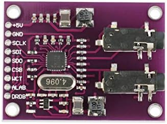
Figure 1: Top view of the ADS1293 module. This image displays the pin headers on the left, including power (+5V, GND), communication (SCLK, SDI, SDO, CSB), and control pins (HCT, ALAB, DRDB). Two 3.5mm audio jack connectors are visible on the right, typically used for sensor inputs. The main ADS1293 IC and a crystal oscillator are centrally located.
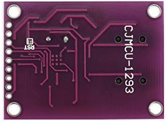
Figure 2: Bottom view of the ADS1293 module. This view shows the solder pads and traces on the underside of the PCB. The text 'CJMCU-1293' is clearly visible, indicating the board's identifier.
3. Setup
Before connecting the module, ensure your development environment (e.g., microcontroller, power supply) is ready.
3.1. Power Supply Connection
- Connect the +5V pin on the module to a stable 5V DC power source.
- Connect the GND pin on the module to the ground of your power supply and microcontroller.
- Ensure the power supply can provide sufficient current for the module and any connected sensors.
3.2. Data Interface Connection (SPI)
The ADS1293 primarily uses a Serial Peripheral Interface (SPI) for communication with a host microcontroller.
- SCLK (Serial Clock): Connect to your microcontroller's SPI clock (SCK) pin.
- SDI (Serial Data In): Connect to your microcontroller's SPI Master Out Slave In (MOSI) pin.
- SDO (Serial Data Out): Connect to your microcontroller's SPI Master In Slave Out (MISO) pin.
- CSB (Chip Select Bar): Connect to a digital output pin on your microcontroller. This pin should be driven low to select the ADS1293 for communication.
3.3. Sensor Input Connection
Connect your biopotential electrodes or sensors to the 3.5mm audio jack inputs on the module. Refer to your sensor's documentation for proper wiring to the audio jack pins (tip, ring, sleeve).
4. Operating Instructions
Operating the ADS1293 module involves configuring its internal registers via SPI and then reading the converted data.
4.1. Initialization Sequence
- Power Up: Apply power to the module as described in Section 3.1.
- Reset: Send a software reset command via SPI or toggle the RST pin (if available and connected) to ensure the device is in a known state.
- Register Configuration: Write to the ADS1293's configuration registers via SPI to set up channel inputs, gain, data rate, lead-off detection, and other operational parameters according to your application requirements. Refer to the ADS1293 datasheet for a complete list of registers and their functions.
- Start Conversion: Issue the command to start continuous data conversion.
4.2. Data Acquisition
Once conversions have started, data can be read from the module.
- The ADS1293 will assert an interrupt (e.g., via the DRDY pin, if configured) when new conversion data is ready.
- Your microcontroller should then read the data from the output registers via SPI. The data will typically be 24-bit per channel.
- Process the acquired digital data as needed for your application (e.g., filtering, display, storage).
5. Maintenance
Proper care ensures the longevity and reliable performance of your ADS1293 module.
5.1. Cleaning
- Ensure the module is powered off and disconnected from all sources before cleaning.
- Use a soft, dry, lint-free cloth to gently wipe the module.
- For stubborn dirt, a cloth lightly dampened with isopropyl alcohol (IPA) can be used, ensuring no liquid enters connectors or components. Allow to dry completely before re-powering.
- Avoid using abrasive cleaners, solvents, or excessive moisture.
5.2. Storage
- Store the module in a cool, dry place, away from direct sunlight and extreme temperatures.
- Keep the module in an anti-static bag when not in use to prevent electrostatic discharge (ESD) damage.
- Avoid storing in environments with high humidity or corrosive gases.
6. Troubleshooting
If you encounter issues with your ADS1293 module, refer to the following common problems and solutions.
6.1. Common Issues
- No Power/Module Not Responding:
- Check all power connections (+5V, GND) for proper voltage and continuity.
- Ensure your power supply is providing stable voltage and sufficient current.
- No Data or Incorrect Data via SPI:
- Verify all SPI connections (SCLK, SDI, SDO, CSB) are correct and secure.
- Check your microcontroller's SPI configuration (clock polarity, phase, speed).
- Ensure the CSB pin is correctly toggled (low to select, high to deselect).
- Confirm the ADS1293 registers are configured correctly for data acquisition.
- Check for proper initialization sequence as described in Section 4.1.
- Noisy or Unexpected Sensor Readings:
- Verify sensor connections are secure and correctly wired to the audio jacks.
- Check for external electrical interference; try operating in a shielded environment.
- Ensure proper grounding of your entire system.
- Review ADS1293 register settings for gain, input multiplexer, and filter configurations.
- Inspect sensors for damage or improper contact.
7. Specifications
Technical specifications for the JESSINIE ADS1293 module.
| Parameter | Value |
|---|---|
| Brand | JESSINIE |
| Model Name | ADS1293 |
| Channels | 3 |
| Resolution | 24-bit |
| Connectivity Technology | SPI (I2C mentioned in source, but SPI is primary for ADS1293) |
| Analog Supply Voltage | 2.7 V to 5.5 V |
| Digital I/O Supply Voltage | 1.65 V to 3.6 V |
| Data Rate | Up to 25.6 ksps |
| Input Bias Current | 175 pA |
| Differential Input Voltage Range | ±400 mV |
| Compatible Devices | SPI compatible microcontrollers, devices using AL ARMB pin for diagnostics |
8. Warranty and Support
For warranty information, technical support, or further inquiries regarding your JESSINIE ADS1293 module, please contact the manufacturer or your point of purchase. Ensure you have your product model and purchase details available when seeking support.
Ask a question about this manual
Ask about setup, troubleshooting, compatibility, parts, safety, or missing instructions. Manuals+ will review the question and use this page’s manual context to help answer it.