1. Introduction
This manual provides essential instructions for the installation, operation, and maintenance of your PNI Greenhouse SC1800C PRO 3KW Hybrid Solar Inverter. This multi-functional inverter/charger combines the functions of an inverter, solar charger, and battery charger to offer uninterrupted power support in a portable design. Please read this manual thoroughly before installation and use to ensure optimal performance and safety.
2. Safety Instructions
WARNING: This section contains critical safety information. Failure to follow these instructions may result in serious injury or damage to the equipment.
- Installation and wiring must be performed by qualified personnel only.
- Do not attempt to disassemble or repair the unit yourself. Refer all servicing to authorized service personnel.
- Keep children away from the inverter.
- Ensure proper ventilation around the inverter to prevent overheating.
- Do not expose the inverter to rain, snow, spray, or any type of liquid.
- Before connecting or disconnecting any wiring, ensure all power sources (AC, solar, battery) are disconnected.
- Use appropriate circuit breakers and fuses as required by local electrical codes.

Figure 1: Front view of the inverter showing the caution label.
3. Product Overview
3.1 Key Features
- Multi-functional inverter/charger with integrated MPPT solar charge controller.
- Pure sine wave output for sensitive electronics.
- Configurable input voltage range for home appliances and personal computers.
- Configurable battery charging current based on applications.
- Configurable AC/Solar Charger priority via LCD setting.
- Compatible with mains voltage or generator power.
- Automatic restart while AC is recovering.
- Overload, over temperature, and short circuit protection.
- Smart battery charger design for optimized battery performance.
- Cold start function.
- Monitoring with PC software (USB cable included) and optional WiFi dongle for remote monitoring.
3.2 Package Contents
The package includes:
- PNI Greenhouse SC1800C PRO Hybrid Solar Inverter
- USB Communication Cable
- User Manual
3.3 Physical Description
Figure 2: Front view of the inverter.
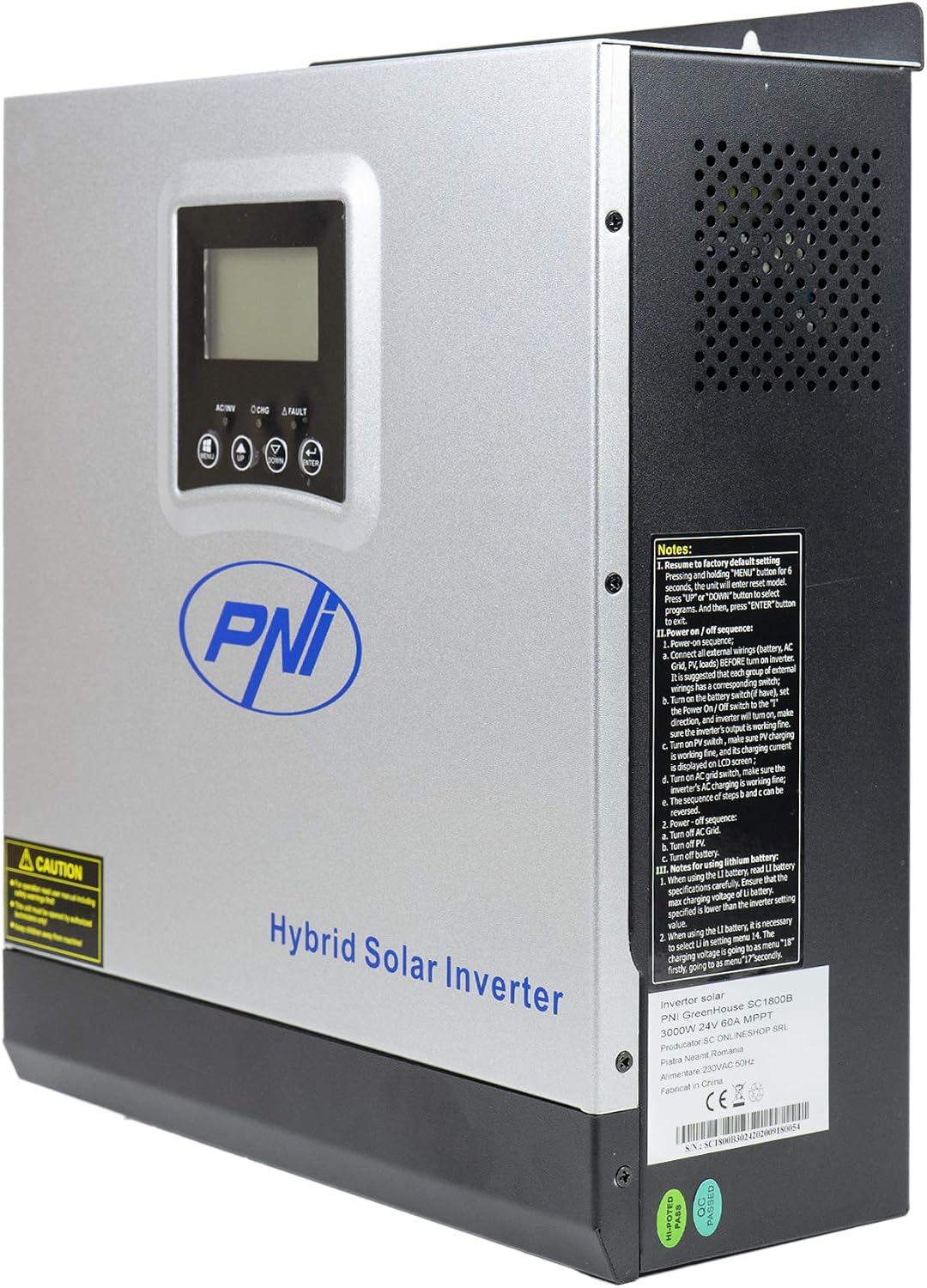
Figure 3: Side view of the inverter, highlighting ventilation and general notes.

Figure 4: Rear panel connections. 1: AC Input, 2: AC Output, 3: ON/OFF Switch, 4: Input Breaker, 5: Battery Terminals (DC+ DC-), 6: PV Input Terminals (PV+ PV-).

Figure 5: Side panel communication ports: COM, USB, and optional WiFi port.
3.4 Application Diagram

Figure 6: Basic application diagram. 1: Solar panels, 2: Utility grid, 3: Generator, 4: Off-Grid solar inverter, 5: Battery, 6: Home loads. Note: Generator, PV modules, WiFi module, and battery are not included.
4. Setup & Installation
4.1 Mounting the Inverter
The inverter is designed for wall mounting. Choose a suitable location that is:
- Indoors and protected from direct sunlight, rain, and dust.
- Well-ventilated to allow for heat dissipation.
- Accessible for wiring and maintenance.
- Strong enough to support the inverter's weight (approximately 7.75 kg).
4.2 Wiring Connections
All wiring must comply with local electrical codes and regulations. Ensure all power sources are disconnected before making any connections.
- Battery Connection: Connect the 24V battery bank to the DC+ and DC- terminals (5 in Figure 4). Ensure correct polarity. The inverter supports AGM, lead-acid, GEL, and user-defined lithium-ion batteries.
- AC Input Connection: Connect the utility grid or generator AC input to the AC INPUT terminals (1 in Figure 4).
- AC Output Connection: Connect your home loads to the AC OUTPUT terminals (2 in Figure 4).
- PV Input Connection: Connect your solar panels to the PV+ and PV- terminals (6 in Figure 4). Ensure the PV input voltage (30-120 VDC) and current (max 30A) are within the inverter's specifications.
IMPORTANT: Double-check all connections for correct polarity and secure fastening before powering on the unit.
5. Operation
5.1 Control Panel

Figure 7: Control Panel. 1: Function Buttons (MENU, UP, DOWN, ENTER), 2: LCD Display, 3: AC/INV Indicator, 4: CHG Indicator, 5: FAULT Indicator.
The LCD display shows system information such as input/output voltage, battery status, load percentage, and operating mode. The function buttons allow you to navigate menus and configure settings.
5.2 Powering On/Off
- To Power On:
a. Ensure all wiring connections are secure.
b. Turn on the battery breaker (if installed).
c. Turn on the PV input breaker (if installed).
d. Turn on the AC input breaker (if connected to utility/generator).
e. Press the ON/OFF switch (3 in Figure 4) on the inverter to the 'ON' position. The inverter will perform a self-test and the LCD will light up. - To Power Off:
a. Disconnect all AC loads from the inverter.
b. Press the ON/OFF switch to the 'OFF' position.
c. Turn off the AC input breaker.
d. Turn off the PV input breaker.
e. Turn off the battery breaker.
5.3 Operating Modes
The inverter supports various operating modes, configurable via the LCD menu:
- SBU (Solar-Battery-Utility) Priority: Solar power is the primary source, followed by battery, then utility grid.
- UTI (Utility) Priority: Utility grid is the primary source, followed by solar, then battery.
- SOL (Solar) Priority: Solar power is the primary source, followed by utility grid, then battery.

Figure 8: Illustration of various operating and charging modes.
5.4 Monitoring and Communication
- USB Communication: Connect the inverter to a PC using the provided USB cable (Figure 5) to monitor system status and configure advanced settings via dedicated software.
- Optional WiFi Dongle: For remote monitoring via mobile app or PC, an optional WiFi dongle can be connected to the designated port (Figure 5).
6. Maintenance
Regular maintenance ensures the longevity and optimal performance of your inverter.
- Cleaning: Periodically clean the exterior of the inverter and ensure ventilation openings are free from dust and debris. Use a dry cloth.
- Connections: Annually check all electrical connections for tightness and signs of corrosion.
- Battery Health: Monitor battery voltage and health, especially for lead-acid batteries, to ensure they are functioning correctly.
- Environment: Ensure the operating environment remains within the specified temperature range (-26°C to +80°C) and humidity levels.
CAUTION: Disconnect all power sources before performing any maintenance.
7. Troubleshooting
This section provides basic troubleshooting steps for common issues. For more complex problems, contact technical support.
| Problem | Possible Cause | Solution |
|---|---|---|
| Inverter does not turn on | No battery connection; Battery voltage too low; ON/OFF switch is off | Check battery connections; Charge battery; Turn ON/OFF switch to 'ON' |
| No AC output | Overload; Short circuit; Inverter fault | Reduce load; Check for short circuits; Restart inverter; Contact support if fault persists |
| Battery not charging | PV input too low/disconnected; AC input disconnected; Charger fault | Check PV connections and sunlight; Check AC input; Verify charger settings; Contact support |
| Alarm sounds | Low battery; Overload; Over-voltage; Disconnected battery | Check battery level; Reduce load; Check input voltage; Reconnect battery |
8. Specifications
| Feature | Specification |
|---|---|
| Model Name | SC1800C PRO |
| Rated Power | 3000 W / 3000 VA |
| Peak Power | 6000 VA (0.5 seconds) |
| Battery Voltage | 24 V |
| Compatible Batteries | AGM, Lead-acid, GEL, Lithium-ion (user-defined) |
| Minimum Start-up Voltage | 23 V (cold start) |
| Waveform | Pure Sine Wave |
| Output Frequency | 50, 60 Hz |
| AC Input Voltage | 230 V |
| Max PV Input Power | 2000 W |
| Max PV Input Voltage (Vmp) | 30 - 120 VDC |
| Max Solar Charge Current | 60 A |
| Solar Charger Type | MPPT |
| Max AC Charge Current | 30 A |
| Inverter Efficiency | 90% ~ 93% |
| Transfer Time | 10 ms (UPS), 20 ms (APL) |
| Operating Temperature | -26°C ~ +80°C |
| Dimensions (L x W x H) | 350 x 290 x 120 mm (Product description) / 330 x 290 x 100 mm (Specifications) |
| Weight | 6.9 kg (Product description) / 7.75 kg (Specifications) |
| Standby Consumption | ~25 W (~12.5 W in energy saving mode) |
| Communication | USB, optional WiFi module |
9. Warranty & Support
9.1 Warranty Information
The PNI Greenhouse SC1800C PRO Hybrid Solar Inverter comes with a manufacturer's warranty. Please refer to the warranty card included with your product or contact your retailer for specific warranty terms and conditions. Keep your purchase receipt as proof of purchase.
9.2 Technical Support
For technical assistance, troubleshooting beyond this manual, or service inquiries, please contact PNI customer support or your authorized dealer. Have your product model number and serial number ready when contacting support.


