BTMETER BT-7200CAPP Digital Clamp Meter Multimeter User Manual
Model: BT-7200CAPP
1. Introduction
This manual provides detailed instructions for the safe and effective operation of the BTMETER BT-7200CAPP Digital Clamp Meter Multimeter. This device is designed for measuring AC/DC current, AC/DC voltage, resistance, capacitance, frequency, duty cycle, diode, and continuity. It features True RMS measurement, Non-Contact Voltage (NCV) detection, and Bluetooth connectivity for data export.
2. Safety Information
WARNING: To avoid electric shock or personal injury, read all safety information before using this product.
- Always adhere to local and national safety codes.
- Do not use the meter if it appears damaged or if the test leads are damaged.
- Do not apply more than the rated voltage, as marked on the meter, between terminals or between any terminal and ground.
- Use caution when working with voltages above 30V AC RMS, 42V peak, or 60V DC. These voltages pose a shock hazard.
- Always disconnect the circuit power and discharge all high-voltage capacitors before testing resistance, continuity, diodes, or capacitance.
- Ensure the rotary switch is in the correct position for the desired measurement before connecting test leads.
- When measuring current with the clamp, ensure only one conductor is placed within the clamp jaws. Clamping around multiple conductors carrying current in opposite directions will result in an inaccurate reading of zero.
3. Product Overview
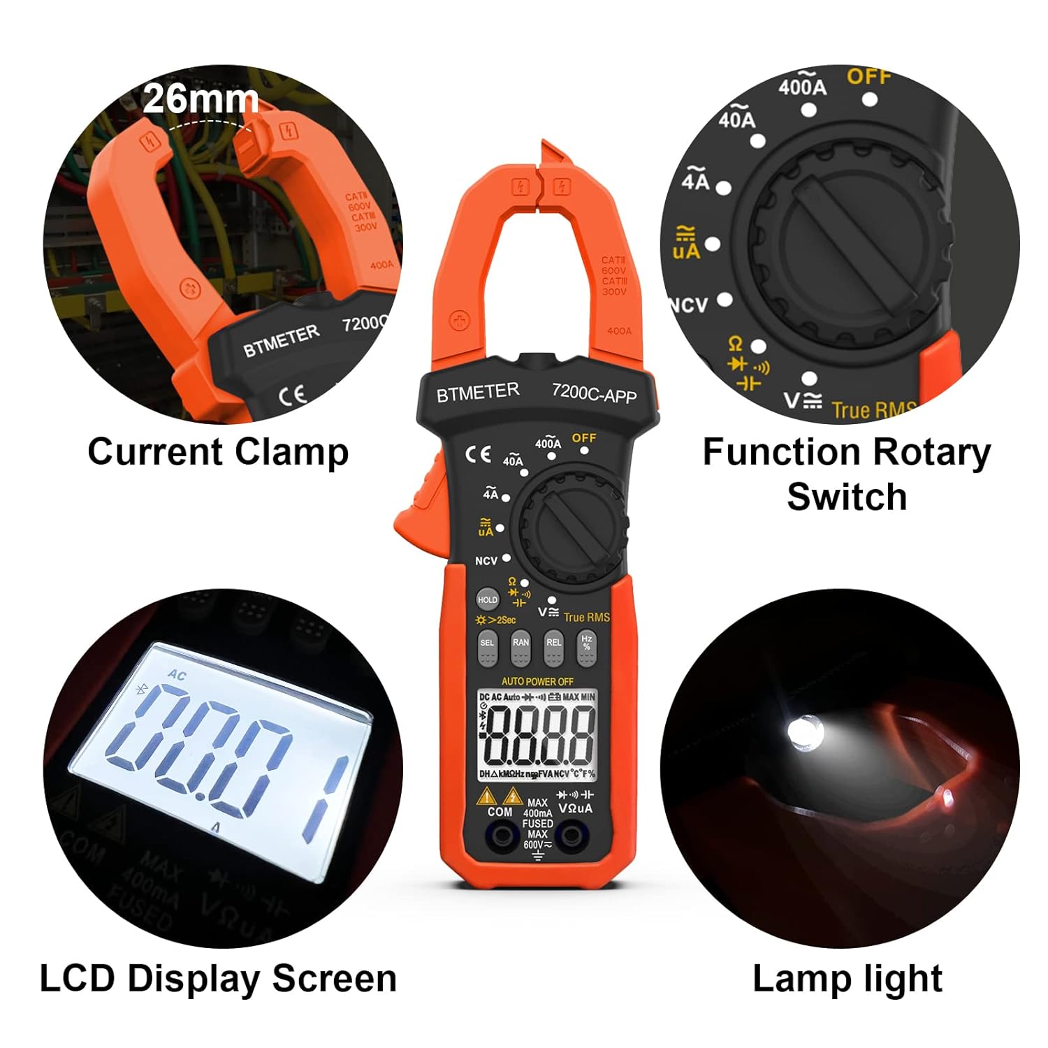
Image: Key components of the BTMETER BT-7200CAPP Digital Clamp Meter, highlighting the current clamp, rotary switch, LCD display, and integrated lamp light.
3.1 Components
- Current Clamp: Used for non-contact AC/DC current measurement. Maximum opening: 26mm.
- Function Rotary Switch: Selects the desired measurement function (e.g., AC/DC Voltage, Resistance, Current).
- LCD Display Screen: Shows measurement readings, units, and function indicators. Features a backlight for low-light conditions.
- Buttons:
- HOLD / ☀ (Backlight): Press briefly to hold the current reading. Press and hold for 2 seconds to turn the display backlight on/off.
- SEL: Selects between different measurement modes within a single rotary switch position (e.g., AC/DC voltage, Diode/Continuity).
- RAN: Manual range selection (if auto-ranging is not desired).
- REL: Relative measurement mode. Also used to zero the current reading before measurement.
- Hz/%: Selects frequency or duty cycle measurement.
- Input Terminals: For connecting test leads for voltage, resistance, capacitance, diode, and continuity measurements.
- NCV Sensor: Non-Contact Voltage detection area.
- LED Flashlight: Illuminates the measurement area.
4. Setup
4.1 Battery Installation
- Ensure the meter is turned OFF.
- Locate the battery compartment on the back of the meter.
- Unscrew the retaining screw and remove the battery cover.
- Insert two AAA batteries, observing correct polarity (+/-).
- Replace the battery cover and secure it with the screw.
4.2 Connecting to the AILink App (Bluetooth)

Image: The BTMETER BT-7200CAPP Clamp Meter wirelessly connected to a smartphone displaying measurement data through the AILink application.
- Download the "AILink" app from your device's app store. You can find download links at aicare.net.cn/app/ailink/download/.
- Enable Bluetooth on your mobile phone.
- Turn on the BT-7200CAPP meter.
- Open the AILink app. The app will search for available devices.
- Select the BT-7200CAPP from the list of found devices to establish a connection.
- Once connected, you can control the meter and monitor measurements remotely from your phone.
5. Operating Instructions
5.1 General Measurement Procedure
- Turn the rotary switch to the desired function.
- Connect the test leads to the appropriate input terminals (if applicable).
- Perform the measurement as described in the specific function sections below.
- Read the measurement value on the LCD display.
5.2 AC/DC Current Measurement (Clamp)

Image: Illustration demonstrating the correct technique for clamping around a single conductor for accurate current measurement.
- Turn the rotary switch to the 40A or 400A position for AC/DC current.
- Press the SEL button to switch between AC and DC current modes if necessary.
- Before clamping, press the REL button to zero the display. This is crucial for accurate current readings, especially DC.
- Open the clamp jaws and enclose only one conductor of the circuit.
- Read the current value on the display.
5.3 AC/DC Voltage Measurement
- Turn the rotary switch to the V∼ (AC Voltage) or V— (DC Voltage) position. The meter will auto-range.
- Insert the red test lead into the VΩHz terminal and the black test lead into the COM terminal.
- Connect the test leads in parallel to the circuit or component under test.
- Read the voltage value on the display.
5.4 Resistance Measurement
- Turn the rotary switch to the Ω position.
- Insert the red test lead into the VΩHz terminal and the black test lead into the COM terminal.
- Ensure the circuit is de-energized before connecting the test leads across the component.
- Read the resistance value on the display.
5.5 Capacitance Measurement
- Turn the rotary switch to the Ω position. Press SEL until the capacitance symbol (†) appears.
- Insert the red test lead into the VΩHz terminal and the black test lead into the COM terminal.
- Ensure the capacitor is fully discharged before connecting the test leads.
- Connect the test leads across the capacitor.
- Read the capacitance value on the display.
5.6 Frequency and Duty Cycle Measurement
- Turn the rotary switch to the Hz/% position.
- Insert the red test lead into the VΩHz terminal and the black test lead into the COM terminal.
- Connect the test leads across the signal source.
- Press the Hz/% button to toggle between frequency (Hz) and duty cycle (%).
- Read the value on the display.
5.7 Diode Test
- Turn the rotary switch to the Ω position. Press SEL until the diode symbol (→|—) appears.
- Insert the red test lead into the VΩHz terminal and the black test lead into the COM terminal.
- Connect the red test lead to the anode and the black test lead to the cathode of the diode.
- Read the forward voltage drop. Reverse the leads to check for open circuit (OL) indication.
5.8 Continuity Test

Image: The BTMETER BT-7200CAPP Clamp Meter conducting a continuity test, illustrating the use of test leads and the device's physical dimensions.
- Turn the rotary switch to the Ω position. Press SEL until the continuity symbol (♫) appears.
- Insert the red test lead into the VΩHz terminal and the black test lead into the COM terminal.
- Connect the test leads across the circuit or component.
- If the resistance is less than approximately 50Ω, the buzzer will sound, and the LED light will illuminate, indicating continuity.
5.9 Non-Contact Voltage (NCV) Detection
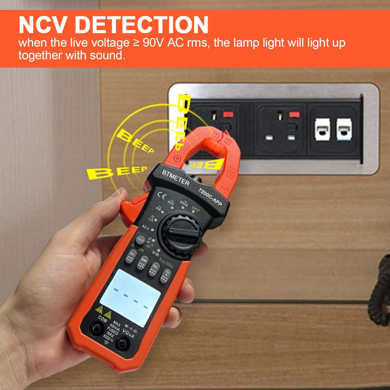
Image: The BTMETER BT-7200CAPP Clamp Meter detecting live AC voltage without contact, indicated by beeping and a flashing light.
- Turn the rotary switch to the NCV position.
- Move the NCV sensor area of the meter close to a live AC voltage source (e.g., an electrical outlet or insulated wire).
- If live AC voltage ≥ 90V RMS is detected, the meter will emit an audible beep and the NCV indicator light will flash.
5.10 Data Hold, Backlight, and Auto Power Off
- Data Hold: Press the HOLD button briefly to freeze the current reading on the display. Press again to release.
- Backlight: Press and hold the HOLD button for approximately 2 seconds to turn the display backlight on or off.
- LED Flashlight: The flashlight button is typically located on the side or front of the meter. Press it to turn the flashlight on/off.
- Auto Power Off: The meter will automatically power off after approximately 15 minutes of inactivity to conserve battery life. This feature can usually be disabled by holding down a specific button (refer to the meter's on-device markings or full manual for details) while turning it on.
6. Data Export and App Usage

Image: The AILink app interface on a smartphone, showing live data from the connected BTMETER BT-7200CAPP.
The AILink app enhances the functionality of your BT-7200CAPP by allowing remote monitoring and data management.
- Real-time Display: View live measurement data directly on your smartphone screen.
- Data Recording: Record measurement data over time for analysis.
- Data Export: Export recorded data in various formats (e.g., CSV) for further processing on a computer.
- Remote Control: Some functions of the meter may be controllable via the app.
For detailed instructions on app features, refer to the in-app help or the full digital manual available through the app.


