
1. Introduction
This manual provides detailed instructions for the safe and effective operation of the WapoRich RQ-39C Digital Multimeter. The RQ-39C is a True RMS 6000-count auto-ranging multimeter designed for measuring AC/DC voltage, AC/DC current, resistance, capacitance, frequency, temperature, diode, continuity, and hFE transistor values. It is suitable for professional, educational, and home use.
2. Safety Information
To ensure safe operation, always adhere to the following safety precautions:
- Read and understand all instructions in this manual before using the multimeter.
- Never apply voltage or current that exceeds the maximum specified limits for the meter.
- Use caution when working with voltages above 30V AC RMS, 42V peak, or 60V DC. These voltages pose a shock hazard.
- Always disconnect the test leads from the circuit before changing functions or ranges.
- Inspect test leads for damaged insulation or exposed metal before each use. Replace if damaged.
- Ensure the battery cover is securely closed before operation.
- Do not operate the meter if it appears damaged or if it is not operating properly.
- Do not operate the meter in explosive gas, vapor, or dust environments.
- Always use the correct terminals, function, and range for your measurement.
3. Package Contents
Verify that all items are present in the package:
- 1 x WapoRich RQ-39C Digital Multimeter
- 1 x 9V Battery
- 1 x User Manual (English)
- 2 x Test Leads (one red, one black)
- 1 x Thermocouple Temperature Probe
- 1 x Wrist Strap
- 1 x Screwdriver

Image: Contents of the WapoRich RQ-39C Digital Multimeter package. Includes the multimeter, test leads, 9V battery, user manual, thermocouple probe, wrist strap, and a screwdriver.
4. Product Features and Components
Familiarize yourself with the multimeter's layout and functions:

Image: Front panel of the WapoRich RQ-39C Digital Multimeter with numbered components.
- NCV Detection Area: Used for Non-Contact Voltage detection.
- CDS Sensor: Automatic control of LCD backlight.
- LCD Display: Shows measurement readings and full function symbols.
- SELECT Key: Used to switch between functions within a range (e.g., AC/DC, Diode/Continuity).
- HOLD Key: Locks the current display value.
- CDS Sensor: Automatic control of LCD backlight.
- REL Key: Activates relative measurement mode.
- Hertz / % Key: Used for Frequency or Duty Cycle measurements.
- Range Switch: Rotary dial to select measurement functions.
- Input Jacks:
- 10A Jack: For 10A current measurements.
- COM Jack: Common (negative) input for all measurements.
- VΩmA Jack: Positive input for Voltage, Resistance, Capacitance, Frequency, Temperature, Diode, Continuity, and mA/µA current measurements.
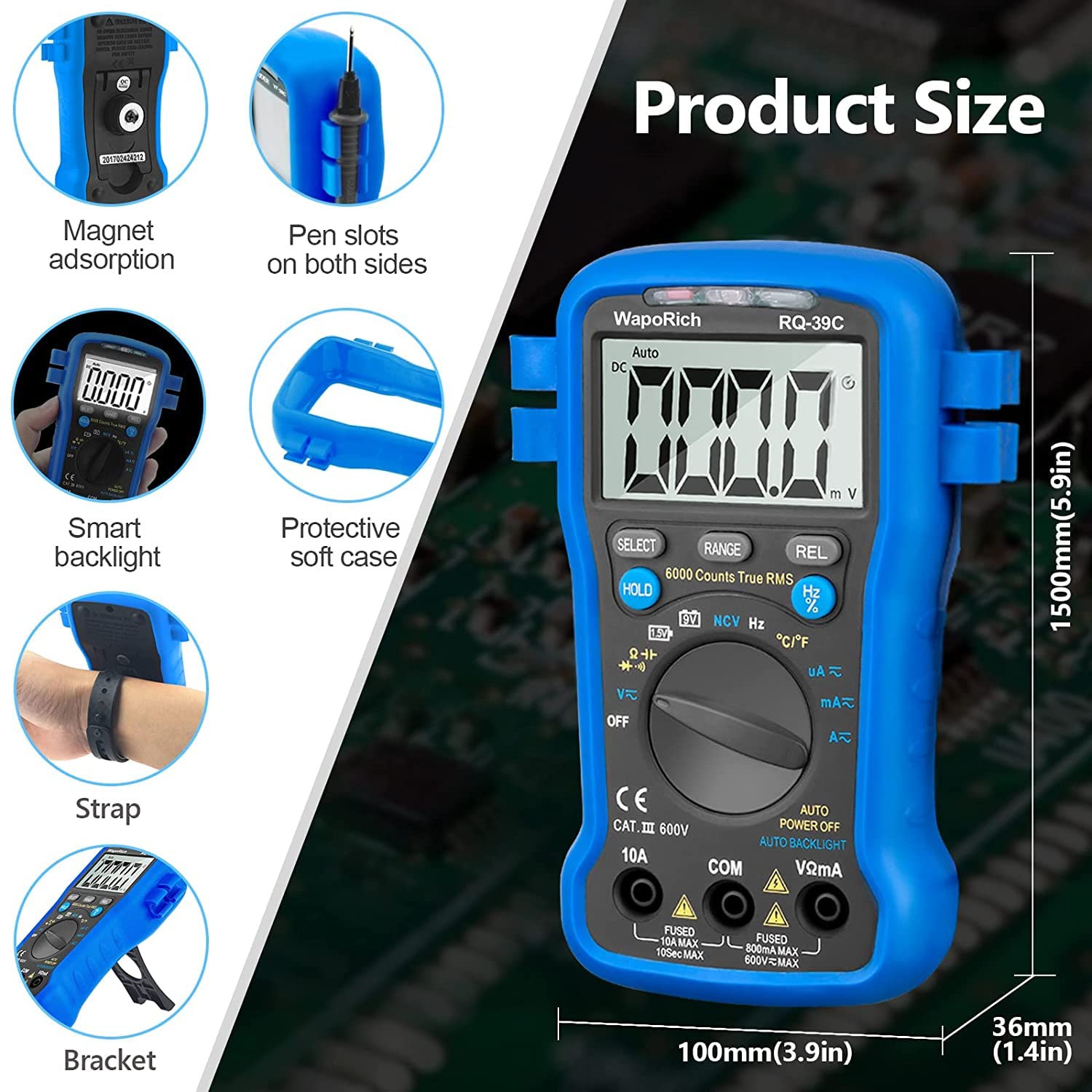
Image: WapoRich RQ-39C Digital Multimeter with dimensions and additional features. Features include magnet adsorption, pen slots on both sides, smart backlight, protective soft case, strap, and a bracket.
Additional Features:
- Magnet Adsorption: Allows the meter to be attached to metal surfaces for hands-free operation.
- Pen Slots: Conveniently store test leads on the sides of the meter.
- Smart Backlight: Automatic backlight for clear readings in various lighting conditions.
- Protective Soft Case: Provides durability and protection against impacts.
- Back Bracket: Integrated kickstand for angled viewing and easier measurement.
5. Setup
5.1 Battery Installation
- Ensure the multimeter is turned OFF.
- Locate the battery compartment on the back of the meter.
- Use the provided screwdriver to loosen the screw on the battery cover.
- Remove the battery cover.
- Connect the 9V battery to the battery clips, observing correct polarity.
- Place the battery into the compartment and replace the cover, securing it with the screw.
5.2 Connecting Test Leads

Image: Diagram illustrating the correct connection of test leads to the WapoRich RQ-39C Multimeter. The black lead connects to the COM jack, and the red lead connects to the VΩHzT jack for most measurements.
- Always insert the black test lead into the COM (Common) jack.
- For most measurements (Voltage, Resistance, Capacitance, Frequency, Temperature, Diode, Continuity, mA/µA current), insert the red test lead into the VΩmA jack.
- For high current measurements (up to 10A), insert the red test lead into the 10A jack.
6. Operating Instructions
The RQ-39C features auto-ranging for most functions, simplifying operation. Rotate the function switch to the desired measurement type.

Image: The WapoRich RQ-39C Digital Multimeter demonstrating various measurement capabilities including temperature, continuity, NCV, and voltage tests.
6.1 DC/AC Voltage Measurement
- Insert the black lead into the COM jack and the red lead into the VΩmA jack.
- Rotate the function switch to the V~ (AC Voltage) or V- (DC Voltage) position. The meter will automatically select the appropriate range.
- Press the SELECT button to toggle between AC and DC voltage if the switch position covers both.
- Connect the test leads in parallel to the circuit or component under test.
- Read the voltage value on the LCD display.

Image: The multimeter measuring the voltage of a 9V battery and an AC wall outlet.
6.2 DC/AC Current Measurement (mA/µA)
- Insert the black lead into the COM jack and the red lead into the VΩmA jack.
- Rotate the function switch to the mA~ (AC Current) or mA- (DC Current) position.
- Press the SELECT button to toggle between AC and DC current if the switch position covers both.
- Connect the test leads in series with the circuit.
- Read the current value on the LCD display.
6.3 High Current Measurement (10A)
- IMPORTANT: Move the red test lead from the VΩmA jack to the 10A jack.
- Rotate the function switch to the 10A~ (AC Current) or 10A- (DC Current) position.
- Press the SELECT button to toggle between AC and DC current if the switch position covers both.
- Connect the test leads in series with the circuit.
- Read the current value on the LCD display.
6.4 Resistance Measurement
- Insert the black lead into the COM jack and the red lead into the VΩmA jack.
- Rotate the function switch to the Ω (Resistance) position.
- Ensure the circuit or component is de-energized before measuring resistance.
- Connect the test leads across the component.
- Read the resistance value on the LCD display.
6.5 Capacitance Measurement
- Insert the black lead into the COM jack and the red lead into the VΩmA jack.
- Rotate the function switch to the Capacitance position (often shared with Diode/Continuity, use SELECT to cycle).
- Ensure the capacitor is fully discharged before measurement to prevent damage to the meter.
- Connect the test leads across the capacitor terminals.
- Read the capacitance value on the LCD display.
6.6 Temperature Measurement
- Insert the black lead of the thermocouple into the COM jack and the red lead into the VΩmA jack.
- Rotate the function switch to the °C/°F (Temperature) position.
- Press the SELECT button to toggle between Celsius and Fahrenheit.
- Place the thermocouple tip on or in the object whose temperature is to be measured.
- Read the temperature value on the LCD display.

Image: The multimeter measuring the temperature of a liquid using the included thermocouple probe.
6.7 NCV (Non-Contact Voltage) Detection
- Rotate the function switch to the NCV position.
- Move the NCV detection area (top of the meter) close to the conductor or outlet you wish to test for AC voltage.
- The meter will beep and an LED indicator will flash if AC voltage is detected, with the frequency of beeps and flashes increasing with stronger signals.

Image: The multimeter performing Non-Contact Voltage (NCV) detection near an electrical outlet, indicated by a red flashing light and 'BEEP' text.
6.8 Frequency / Duty Cycle Measurement
- Insert the black lead into the COM jack and the red lead into the VΩmA jack.
- Rotate the function switch to the Hz/% position.
- Press the Hz/% button to toggle between frequency and duty cycle measurements.
- Connect the test leads across the circuit where frequency or duty cycle is to be measured.
- Read the value on the LCD display.
6.9 Diode Test
- Insert the black lead into the COM jack and the red lead into the VΩmA jack.
- Rotate the function switch to the Diode/Continuity position (often shared, use SELECT to cycle).
- Connect the red lead to the anode and the black lead to the cathode of the diode.
- Read the forward voltage drop on the display. Reverse the leads; the display should show OL (Open Loop) for a good diode.
6.10 Continuity Test
- Insert the black lead into the COM jack and the red lead into the VΩmA jack.
- Rotate the function switch to the Diode/Continuity position (often shared, use SELECT to cycle).
- Connect the test leads across the circuit or component.
- If continuity exists (resistance below approximately 50Ω), the buzzer will sound.
6.11 hFE Transistor Test
This multimeter model may include a dedicated hFE socket or a function on the rotary switch. Refer to the specific markings on your device. Insert the transistor leads (Emitter, Base, Collector) into the corresponding holes for NPN or PNP transistors. The display will show the hFE value.
6.12 Data Hold Function
Press the HOLD button to freeze the current reading on the display. Press it again to release the hold function.
6.13 Relative Measurement (REL)
Press the REL button to store the current reading as a reference value. Subsequent measurements will be displayed as the difference from this reference. Press again to exit relative mode.
6.14 Auto Power Off
The multimeter will automatically power off after a period of inactivity to conserve battery life. To reactivate, turn the function switch to OFF and then back to the desired function.
7. Maintenance
7.1 Cleaning
Wipe the meter with a damp cloth and mild detergent. Do not use abrasives or solvents. Ensure the meter is completely dry before use.
7.2 Battery Replacement
When the battery symbol appears on the LCD, replace the 9V battery as described in Section 5.1. Remove the battery if the meter is not used for extended periods.
7.3 Fuse Replacement
If the current measurement function fails, the fuse may need replacement. Refer to the specifications for the correct fuse type and rating. Fuse replacement should only be performed by qualified personnel.
8. Troubleshooting
- No display or dim display: Check battery level and connections. Replace battery if low.
- Incorrect readings: Ensure correct function and range are selected. Check test lead connections and integrity. Verify the circuit is de-energized for resistance/capacitance measurements.
- Current measurement not working: Check if the fuse is blown. Replace if necessary (refer to Section 7.3). Ensure test leads are in the correct current jacks (mA/µA or 10A).
- "OL" displayed: Indicates overload or open circuit. For resistance, it means the resistance is too high or the circuit is open. For voltage/current, it means the input exceeds the meter's range.
9. Specifications
| Specification | Value |
|---|---|
| Brand | WapoRich |
| Model Number | RQ-39C |
| Measurement Type | Voltmeter (Multimeter) |
| Style | Digital |
| Power Source | Battery Powered (9V) |
| Display | 6000 Counts LCD with Backlight |
| DC Voltage Range | 400mV ~ 450V |
| AC Voltage Range | 4V ~ 450V |
| Resistance Range | 400Ω ~ 40MΩ |
| Continuity Test | 400Ω |
| Temperature Range | -20°C to 1000°C / -4°F to 1832°F |
| Dimensions (Package) | 18.2 x 12.2 x 5.9 cm |
| Weight (Package) | 440 grams |
| Included Components | Multimeter, Manual, Test Leads, Thermocouple, Battery, Wrist Strap, Screwdriver |
10. Warranty and Support
WapoRich is committed to providing quality products and customer satisfaction.
- Quality Warranty: This product comes with a 365-day quality warranty.
- Customer Service: Friendly customer service is available 24 hours.
- Technical Support: Lifetime technical support is provided for this product.
For support or warranty claims, please contact WapoRich customer service through your purchase platform or the contact information provided with your product.