Introduction
This manual provides detailed instructions for the installation, operation, and maintenance of the Kaleinavi 12V 4-Channel Wireless Remote Control Switch Module, Model 03. Please read this manual thoroughly before use to ensure proper functionality and safety.

Image: The Kaleinavi 12V 4-Channel Wireless Remote Control Switch Module (green circuit board) and its accompanying 4-button remote control.
Package Contents
- 1 x Receiver Module
- 1 x Remote Control (with battery included)
Specifications
| Parameter | Value |
|---|---|
| Power Supply (Operating Voltage) | DC 12V |
| Relay Current Rating | 10A |
| Output Current | Less than 3A |
| Operating Current | <7mA |
| Sensitivity | -107 dBm |
| Operating Temperature | -40°C to 80°C |
| Module Dimensions | 74 mm x 55 mm x 28 mm |
| Frequency | 433 MHz |
| Remote Distance | Up to 500m (in open field) |
| Coding Method | Learning Code |
| Compatible Devices | Electric Door, Garage Door, Gate, Lamp, Lifter, Motor, Winch |
Setup and Wiring
The receiver module and remote control are pre-paired and tested before shipment. No additional pairing is required upon receipt. Install the module according to the wiring diagrams below.
Receiver Module Overview

Image: Close-up view of the receiver module highlighting key components: the 'Learn' button, jumper for control mode selection (S1, T, L), power input terminals (+U, -U), and relay output terminals (NO, COM, NC for each of the four channels).
- Learn Button: Used for pairing new remote controls or clearing existing codes.
- Jumper (S1, T, L): Configures the receiver's work mode (Toggle, Momentary, Latched).
- Power Input: Connect DC 12V power supply to the +U and -U terminals.
- Relay Outputs: Each channel has Normally Open (NO), Common (COM), and Normally Closed (NC) terminals for connecting loads.
Wiring Diagrams
1. Control 12V DC Loads
This diagram illustrates how to connect 12V DC loads (e.g., lamps) to the receiver module. Ensure the power supply matches the load voltage.
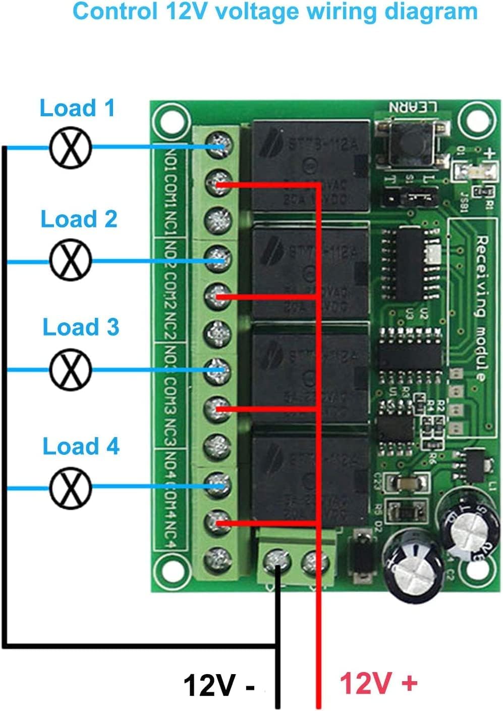
Image: Wiring diagram showing a 12V power source connected to the receiver module's power input. Four separate 12V loads are connected to the COM and NO terminals of each relay channel. The negative terminal of the 12V power source is also connected to one side of each load.
2. Control Other Voltage AC/DC Loads
This diagram shows how to control loads with different voltages (e.g., AC mains voltage) using the relay's dry contact output. The receiver module itself still requires a 12V DC power supply.

Image: Wiring diagram demonstrating how to control loads with a voltage different from the module's 12V DC supply. The module is powered by 12V DC. For each load, one side of the load is connected to the 'FireWire' (live AC or positive DC), and the other side of the load is connected to the NO terminal of a relay. The COM terminal of the same relay is connected to the 'Zero line' (neutral AC or negative DC).
3. Control 12V DC Motor Forward/Backward
This diagram illustrates a common application for controlling the direction of a 12V DC motor using two relay channels. This setup allows for forward and reverse operation.

Image: Wiring diagram for controlling two 12V DC motors. For each motor, the motor's terminals are connected to the NO and NC terminals of a relay. The COM terminal of the relay is connected to the 12V DC positive supply. The 12V DC negative supply is connected to the other side of the motor, allowing for polarity reversal and thus direction control.
4. Product Test DC Lamp Wiring Diagram
This image shows a practical example of connecting a DC lamp for testing purposes. This setup can be used to verify the basic functionality of the module.
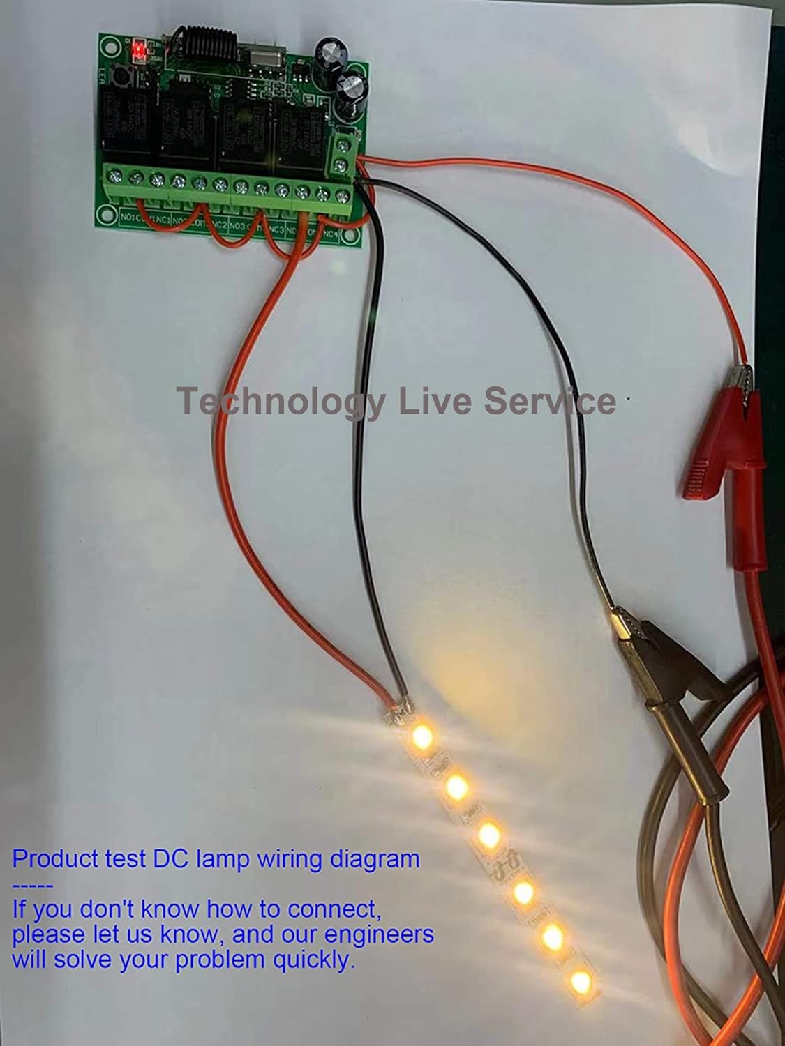
Image: A photograph showing the receiver module connected to a strip of LED lights and a 12V power source via alligator clips, demonstrating a basic test setup for a DC lamp.
Operating Modes
The receiver module supports three operating modes, which can be selected using the jumper on the board.
Jumper Settings
- Toggle (Self-Lock): Jumper placed on S1 + T.
Press the remote button once to turn the relay ON. Press the same button again to turn the relay OFF. Each button controls its corresponding relay independently.
- Momentary (Jog): Jumper placed on S1 (no connection to T or L).
Press and hold the remote button to turn the relay ON. Release the button to turn the relay OFF. Each button controls its corresponding relay independently.
- Latched (Inter-Lock): Jumper placed on S1 + L.
Press one remote button to turn its corresponding relay ON. Press another button to turn the previously ON relay OFF and turn the new button's corresponding relay ON. Only one relay can be ON at a time in this mode.
Learning and Clearing Codes
The module supports learning multiple remote controls and clearing all stored codes.
1. Learning Code
- Press the 'Learn' button on the receiver module. The indicator light will flash.
- Release the 'Learn' button.
- Press any button on the remote control you wish to pair.
- The indicator light on the module will flash two times and then turn off, indicating successful pairing.
The module can learn codes from more than 12 remote controls using PT2262 or EV1527 chips with different codes.
2. Clearing Code
- Press and hold the 'Learn' button on the receiver module for approximately 8 seconds.
- The indicator light will turn on and then turn off, signifying that all stored codes have been successfully cleared.
Remote Control Features
Power Switch
The remote control features a power switch on its side, allowing you to turn it off when not in use to conserve battery life.

Image: Side view of the remote control, showing a small slide switch labeled 'ON/OFF' which controls the remote's power.
Battery Replacement
The remote control uses a 9V battery. To replace the battery, slide open the battery compartment cover on the back of the remote.

Image: The back of the remote control with the battery compartment open, showing a 9V battery next to it, ready for insertion.
Applications
This wireless remote control switch module is suitable for a wide range of applications, including industrial control, security systems, and home automation.

Image: A collage showing various applications: a large crane at a port, a combine harvester in a field, and an irrigation system, illustrating the versatility of the remote control switch in industrial and agricultural settings.
- Controlling electric doors, garage doors, and gates.
- Operating lamps and lighting systems.
- Managing motors, winches, and lifters.
- Integrating into wired door/window control systems and anti-theft alarms for wireless functionality.
Troubleshooting
- Remote Control Not Responding:
- Check if the remote control's power switch is in the 'ON' position.
- Verify the 9V battery in the remote control is correctly installed and has sufficient charge.
- Ensure the remote control is paired with the receiver module. If not, follow the "Learning Code" procedure.
- Receiver Module Not Activating Load:
- Confirm the receiver module is receiving a stable 12V DC power supply.
- Check all wiring connections according to the appropriate wiring diagram. Ensure connections are secure and correct polarity is observed for DC loads.
- Verify the load itself is functional and correctly connected.
- Ensure the operating mode jumper (Toggle, Momentary, Latched) is set correctly for your intended application.
- Reduced Remote Range:
- The stated 500m range is for open fields. Obstacles like trees, walls, and other structures will significantly reduce the effective range.
- Ensure there are no major sources of RF interference near the receiver or remote.
- Check the remote control battery. A low battery can reduce transmission power.
- Interference with Other Devices:
The product uses digital coding to minimize interference. If interference occurs, ensure other 433MHz devices in the vicinity are not using identical coding or channels. Re-pairing the remote might help in some cases.
Maintenance
The Kaleinavi 12V 4-Channel Wireless Remote Control Switch Module is designed for low maintenance. Regular checks include:
- Battery Replacement: Replace the 9V battery in the remote control when its performance degrades or it stops responding.
- Connection Integrity: Periodically inspect all wiring connections to the receiver module to ensure they remain secure and free from corrosion.
- Environmental Conditions: Ensure the module is operated within its specified temperature range (-40°C to 80°C) and protected from excessive moisture or dust.
- Cleaning: Clean the module and remote control with a dry, soft cloth. Avoid using harsh chemicals or abrasive materials.
Warranty and Support
Kaleinavi provides a 1-year warranty for this product. For technical assistance or any questions regarding installation or operation, please contact our customer support. Our engineers are available to help resolve any issues you may encounter.
If you are unsure about wiring connections, please reach out to us for guidance.