
1. Introduction
The REES52 RTU5034 is a versatile GSM-based relay switch designed for remote access control and equipment switching. It allows authorized users to control gates, doors, barriers, and other machinery via a simple phone call, eliminating distance limitations. This device operates on 2G, 3G, and 4G GSM networks, providing a secure and convenient solution for various applications.
2. Safety Information
- Ensure the device is powered by a 9-36V DC supply. Incorrect voltage can damage the unit.
- Always disconnect power before performing any wiring or maintenance.
- Installation should be performed by qualified personnel to prevent electrical hazards.
- Keep the device away from moisture and extreme temperatures.
- Do not attempt to open or repair the device yourself. Contact support for assistance.
3. Package Contents
The package includes:
- 1 x REES52 RTU5034 2G/3G/4G GSM Wireless Gate Opener Relay Switch
4. Key Features
- Supports 2G/3G/4G GSM network communication.
- Remote operation from any location, without distance limitations.
- Wide operating voltage: 9-36V DC with anti-reverse protection.
- Supports up to 200 authorized user numbers.
- Time-based access control for each authorized number.
- Secure operation using caller-ID for identification; unknown callers are ignored.
- Suitable for various applications including gates, bollards, barriers, garage doors, shutters, and access doors.
- Compact design for easy installation.
5. Specifications
| Parameter | Value |
|---|---|
| Model | RTU5034 |
| Device Type | GSM Gate Opener / Remote Relay Switch |
| Operating Voltage | 9-36V DC |
| SIM Card Support | 2G/3G/4G |
| Temperature Range | -10°C to +60°C |
| Humidity Range | Relative humidity 95% (non-condensing) |
| Relay Rating | 3A/220VAC |
| Hardware Interface | Radio Frequency |
| Data Link Protocol | GSM |
| Dimensions (L x W x H) | 90mm x 70mm x 27mm |

Figure 1: RTU5034 Device Dimensions
6. Setup and Installation
6.1. SIM Card Installation
- Ensure the device is powered off.
- Locate the SIM card slot on the RTU5034 unit.
- Insert a 2G/3G/4G compatible SIM card into the slot. Ensure the SIM card is active and has sufficient balance for calls.
- Secure the SIM card if necessary.

Figure 2: Internal Components and SIM Card Slot
6.2. Wiring Connections
The RTU5034 has terminals for power input (DC 9-36V) and relay output (NO, COM, NC).
- Power Input: Connect your 9-36V DC power supply to the DC IN + and - terminals.
- Relay Output: The relay provides Normally Open (NO), Common (COM), and Normally Closed (NC) contacts. Connect your gate opener, lock, or other device to these terminals based on its operational requirements.
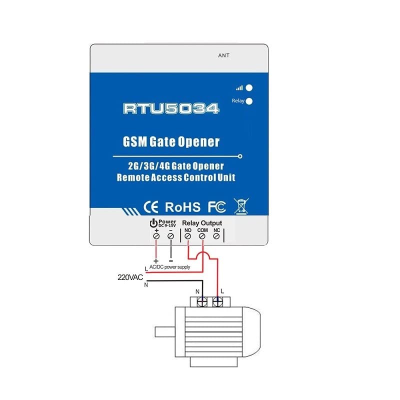
Figure 3: Wiring Example for 220VAC Motor
This diagram illustrates connecting the RTU5034 to a 220VAC motor. The device's relay output controls the power supply to the motor.
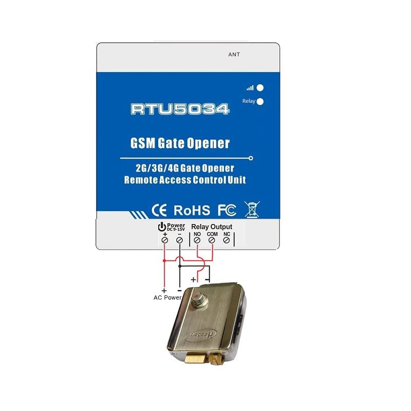
Figure 4: Wiring Example for AC Powered Lock
This diagram shows how to connect the RTU5034 to an AC powered lock, using the relay to control the lock's power.
6.3. Initial Configuration (Programming Authorized Numbers)
The RTU5034 is configured by sending SMS commands to the SIM card number inserted in the device. Refer to the detailed programming guide (usually provided separately or available from the manufacturer) for specific SMS commands.
Key Configuration Steps:
- Set Administrator Number: The first step is typically to set an administrator number that can add or remove other authorized users.
- Add Authorized Users: Send an SMS command from the administrator number to add up to 200 authorized phone numbers.
- Set Relay Activation Time: Configure how long the relay remains active after a call (e.g., 0.5 seconds for a gate pulse).
- Optional: Configure time-based access for specific users.
Note: An optional mobile application may be available for easier configuration. Check the manufacturer's website for details.
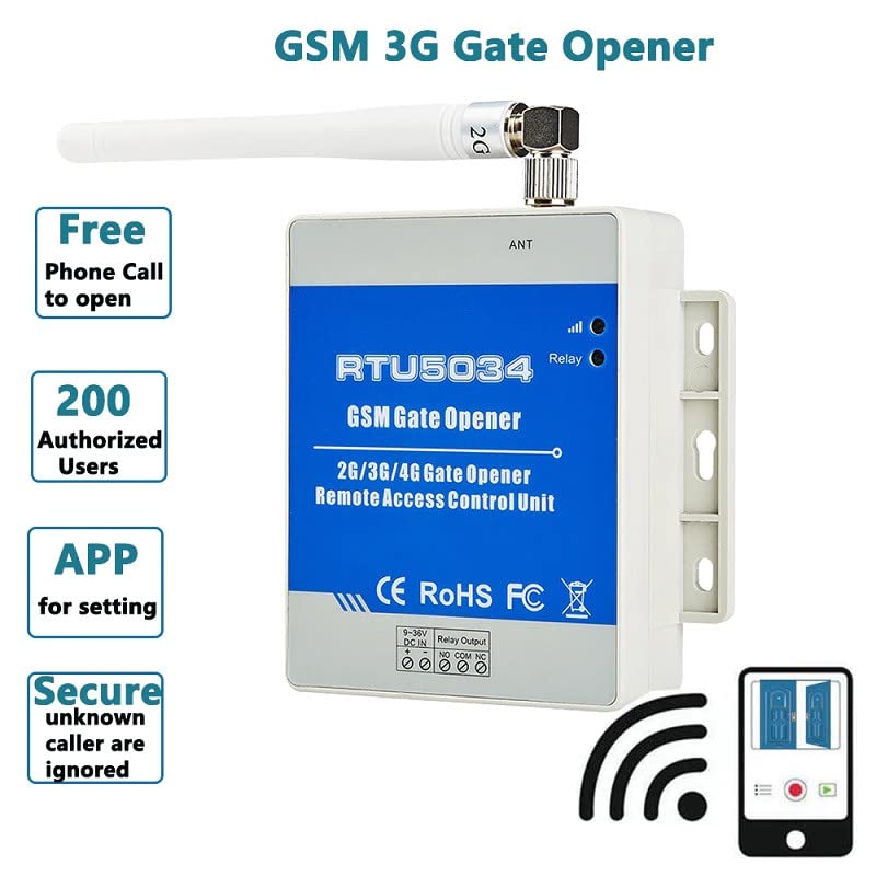
Figure 5: RTU5034 Features Overview, including APP for setting
The device supports up to 200 authorized users and can be configured via an application, simplifying the setup process.
7. Operation
7.1. Opening/Controlling Devices
Once the RTU5034 is set up and authorized numbers are programmed, operating the connected device is straightforward:
- From an authorized mobile phone, dial the phone number of the SIM card inserted in the RTU5034.
- The RTU5034 will recognize the caller ID. If the number is authorized, it will activate its relay for the pre-set duration.
- The device will then reject the call without answering, meaning no call charges are incurred.
- The connected gate, door, or equipment will activate (e.g., open, close, turn on/off).
Note: Calls from unauthorized numbers will be ignored, and the relay will not activate.
8. Maintenance
- Regular Cleaning: Keep the device free from dust and debris. Use a soft, dry cloth for cleaning.
- SIM Card Check: Periodically check the SIM card's balance and expiry to ensure continuous operation.
- Power Supply: Ensure the power supply is stable and within the specified voltage range (9-36V DC).
- Firmware Updates: Check the manufacturer's website for any available firmware updates. Follow instructions carefully if updating.
9. Troubleshooting
| Problem | Possible Cause | Solution |
|---|---|---|
| Device does not respond to calls. |
|
|
| Relay does not activate. |
|
|
| Device appears dead after connection. |
|
|
10. Warranty and Support
10.1. Warranty Information
For warranty details, please contact the manufacturer, REES52. Warranty terms and conditions may vary. Keep your purchase receipt as proof of purchase.
10.2. Technical Support
If you encounter issues that cannot be resolved using the troubleshooting guide, or require further assistance with installation and configuration, please contact REES52 customer support.
- Manufacturer: REES52
- Contact Information: Refer to the product packaging or the official REES52 website for the most current support contact details.