1. Introduction
The LILYGO TTGO T4 V1.3 is an ESP32-based development board integrated with a 2.4-inch ILI9341 LCD. This versatile board offers Wi-Fi and Bluetooth connectivity, making it suitable for a wide range of IoT and embedded projects requiring a display interface. It includes onboard buttons for boot and reset functions, as well as battery power detection capabilities.
2. Product Overview
The TTGO T4 V1.3 development board combines an ESP32 microcontroller with a vibrant 2.4-inch LCD, offering a compact solution for interactive projects. Key features include:
- Microcontroller: ESP32 chip
- Flash Memory: 4MB
- PSRAM: 8MB
- Display: 2.4-inch ILI9341 TFT LCD (320x240 resolution, 65K color display)
- Wireless Connectivity: Wi-Fi (802.11 b/g/n) and Bluetooth (V4.2+BLE)
- Onboard Functions: Boot and Reset buttons, battery power detection
- Programming Platform: Arduino IDE, MicroPython
- Serial Chip: CH9102
- Power Supply: Supports USB and Li-Po battery (JST GH 1.25mm connector)
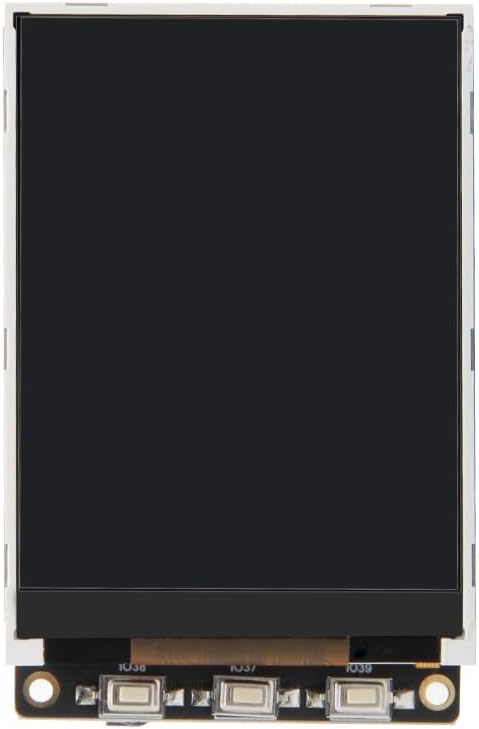
Figure 2.1: Front view of the LILYGO TTGO T4 V1.3 Development Board with the 2.4-inch LCD displaying the LILYGO logo.

Figure 2.2: Back view of the development board, highlighting the various components and connectors.

Figure 2.3: The package includes one TTGO T4 V1.3 board, one Dupont line, and one power cable.
3. Specifications
| Feature | Specification |
|---|---|
| Brand | LILYGO |
| Model Name | T4 V1.3 |
| Wireless Type | Bluetooth, Wi-Fi |
| Operating System | Real-Time Operating System (RTOS) |
| Product Dimensions (LxWxH) | 2.6 x 1.7 x 0.47 inches (66 x 43 x 12 mm) |
| Processor Brand | Espressif (ESP32) |
| Number of Processors | 1 |
| Computer Memory Type | DIMM |
| RAM Memory Installed Size | 8 MB (PSRAM) |
| Memory Storage Capacity | 4 MB (Flash) |
| Display Type | ILI9341 TFT LCD |
| Display Size | 2.4 inch |
| Display Resolution | 320x240 |
| Display Interface | 4-Wire SPI |
| Working Power Supply | 3.3V |
| Battery Connector | JST GH 1.25mm |

Figure 3.1: Physical dimensions of the TTGO T4 V1.3 board.
4. Setup
To begin using your LILYGO TTGO T4 V1.3 development board, follow these general setup steps:
- Power Connection: Connect the board to a power source using the Micro USB port. Alternatively, a Li-Po battery can be connected to the JST GH 1.25mm connector.
- Driver Installation: Ensure you have the necessary USB-to-Serial drivers (for CH9102 chip) installed on your computer. These are typically available from the chip manufacturer's website or through common ESP32 development environment setups.
- Development Environment Setup: Install your preferred development environment, such as Arduino IDE or MicroPython. For Arduino IDE, you will need to add ESP32 board support and the appropriate display libraries (e.g., TFT_eSPI).
- Code Upload: Connect the board to your computer via USB. Select the correct board and COM port in your IDE. Upload your code to the ESP32.
- Resource Access: For detailed code examples, libraries, and further information, refer to the official LILYGO GitHub repository: github.com/Xinyuan-LilyGO/TTGO-T4-TestCode.
5. Operating Instructions
The TTGO T4 V1.3 board is designed for flexible operation, supporting various programming approaches. Once programmed, the board will execute the uploaded firmware.
- Power On/Off: The board powers on automatically when connected to USB or a battery. There is no dedicated power switch.
- Reset Button (RST): A short press of the RST button will restart the ESP32 microcontroller, reloading the current program.
- Boot Button: The Boot button is typically used to put the ESP32 into programming mode. Hold down the Boot button, press and release the RST button, then release the Boot button to enter flash mode for uploading new firmware.
- Display Operation: The 2.4-inch ILI9341 LCD is controlled via the ESP32 using SPI. Your code will manage what is displayed on the screen. Ensure your display library is correctly initialized and configured for the ILI9341 driver.
- Backlight Adjustment: The display backlight can be controlled programmatically, often via PWM, to adjust brightness. Refer to your display library documentation for specific functions.
- Wi-Fi and Bluetooth: Utilize the ESP32's built-in Wi-Fi and Bluetooth capabilities through your code to connect to networks, communicate with other devices, or create access points.
6. Pinout Diagram
Understanding the pinout is crucial for connecting external components and utilizing the full functionality of the TTGO T4 V1.3 board. The following diagram illustrates the pin assignments:

Figure 6.1: LILYGO T4 V1.3 Pinmap. This diagram details the GPIO connections for the ILI9341 LCD, buttons, and other available pins.
Key Pin Assignments:
- ILI9341 TFT LCD: SCLK (IO18), RS (IO32), RST (IO05), SDI (IO23), CS (IO27), SDO (IO12), BL (IO04)
- Buttons: IO38, IO37, IO39
- Power: 3V3, 5V, GND, VBAT (for battery input)
- Micro USB: For charging, powering, burning (uploading firmware), and debugging.
- TF Card: MISO (IO02), SCLK (IO14), MOSI (IO15), CS (IO13)
7. Maintenance
Proper care and maintenance will ensure the longevity and reliable operation of your TTGO T4 V1.3 development board.
- Handling: Handle the board by its edges to avoid touching sensitive components, especially the display and exposed pins.
- Storage: Store the board in an anti-static bag when not in use to protect it from electrostatic discharge. Keep it in a dry environment, away from extreme temperatures.
- Cleaning: If necessary, gently clean the board with a soft, dry brush or compressed air to remove dust. Avoid using liquids or abrasive materials.
- Power Supply: Always use a stable 5V power supply via USB or a compatible Li-Po battery. Ensure correct polarity when connecting a battery.
- Firmware Updates: Regularly check the LILYGO GitHub repository for updated firmware or library versions to benefit from improvements and bug fixes.
8. Troubleshooting
If you encounter issues with your TTGO T4 V1.3 board, consider the following troubleshooting steps:
- Board Not Powering On:
- Verify the USB cable is functional and properly connected to both the board and your computer/power adapter.
- If using a battery, ensure it is charged and correctly connected to the JST connector with the correct polarity.
- Display Remains Blank/Dark:
- Ensure the display library is correctly initialized in your code for the ILI9341 driver.
- Check if the backlight is enabled in your code. Some display libraries require explicit backlight activation.
- Verify all display connections (SPI pins) are correct according to the pinout diagram.
- Failed Firmware Upload:
- Confirm the correct COM port is selected in your IDE.
- Ensure the ESP32 is in flash mode (hold Boot, press/release RST, then release Boot).
- Install or update the USB-to-Serial drivers (CH9102).
- Try a different USB cable or port.
- Wi-Fi/Bluetooth Connectivity Issues:
- Double-check your network credentials (SSID, password) in your code.
- Ensure the Wi-Fi/Bluetooth antenna (if external) is properly connected.
- Verify that the ESP32's Wi-Fi/Bluetooth functions are correctly initialized in your program.
9. Warranty and Support
For warranty information and technical support, please refer to the official LILYGO website or contact your point of purchase. Detailed documentation, community forums, and additional resources can often be found on the LILYGO GitHub page linked in the Setup section.


