1. Introduction
This manual provides detailed instructions for the Diymore SX1262 LoRa V3 ESP32 development board. It covers product features, setup procedures, operational guidelines, maintenance tips, and troubleshooting information to help users effectively utilize the board for various IoT and embedded projects.
Key Features:
- Microprocessor: ESP32-S3FN8 (Xtensa 32-bit LX7 Dual Core, up to 240 MHz) with SX1262 LoRa node chip.
- Connectivity: Integrated Wi-Fi, LoRa, and Bluetooth network connections.
- Interface: USB Type-C with full voltage regulator, ESD protection, short-circuit protection, and RF shielding.
- Display: Integrated 0.96-inch 128x64 dot matrix OLED screen for debugging and information display.
- USB to Serial Chip: CP2102 for convenient program uploading and debugging.
- Battery Management: Integrated SH1.25-2 battery interface with lithium battery management system (charging, discharging, overcharge protection, power detection, automatic USB switching).

Figure 1.1: The Diymore SX1262 LoRa V3 ESP32 Development Board, showcasing the main board with an OLED display, along with an antenna and pin headers for connectivity.
2. Product Overview
2.1 Components and Layout
The Diymore SX1262 LoRa V3 board integrates several key components for its functionality. Understanding their placement is crucial for proper use.

Figure 2.1: Top and bottom views of the development board with key components labeled, including programming keys, Type-C interface, WiFi antenna, OLED display, ESP32 chip, CP2102 chip, power/signal indicators, reset button, LoRa antenna interface, and lithium battery interface.
2.2 Pinout Diagram
The board features extensive pin headers for various connections. Refer to the pinout diagram for detailed information on each pin's function.

Figure 2.2: Comprehensive pinout diagram illustrating the physical pins, power, GND, ADC/DAC, Serial/SPI/I2C, and other connected functionalities for both Header J3 and Header J2.
3. Setup
3.1 Software Setup (Arduino IDE)
To program the Diymore SX1262 LoRa V3 ESP32 board, you will need to set up the Arduino IDE with the necessary board definitions and libraries.
- Open Arduino IDE and Preferences:
Open the Arduino IDE. Navigate to File > Preferences.
Figure 3.1: Screenshot showing the Arduino IDE menu with 'File' and 'Preferences' highlighted.
- Input ESP32 Package URL:
In the Preferences window, locate the "Additional Boards Manager URLs" field. Add the following URL:https://resource.heltec.cn/download/package_heltec_esp32_index.json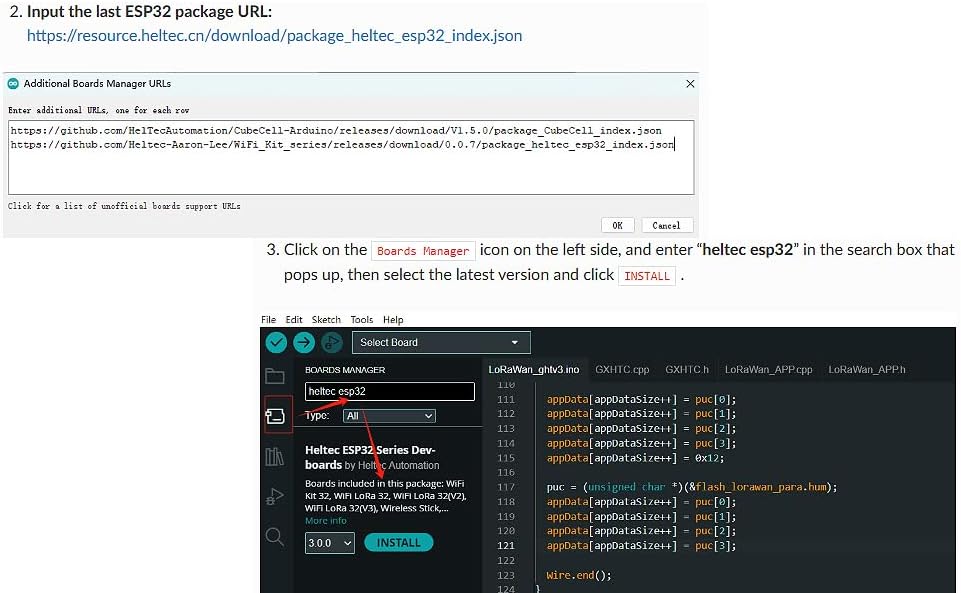
Figure 3.2: The 'Additional Boards Manager URLs' dialog box in Arduino IDE, where the Heltec ESP32 package URL is entered.
- Install Heltec ESP32 Boards:
Go to Tools > Board > Boards Manager.... In the Boards Manager, search for "heltec esp32". Select the latest version of "Heltec ESP32 Series Dev-boards" and click Install. - Install Heltec ESP32 Extended Library:
The Heltec ESP32 Library depends on the Heltec Frame Work and contains extended examples for LoRa/LoRaWAN, factory test code, display examples, sensor examples, and GPS examples.
Click on the Library Manager icon (usually a book icon) on the left side of the Arduino IDE. Search for "HELTEC ESP32", select the latest version, and click Install.
Figure 3.3: Screenshot of the Arduino IDE Library Manager, showing the search results for 'HELTEC ESP32' and the option to install the library.
3.2 Firmware and Examples
Users can download firmware and example code from the official Heltec GitHub repository. This provides a rich set of examples to get started with LoRa, WiFi, and Bluetooth functionalities.

Figure 3.4: Screenshot of the Heltec WiFi_Kit_series GitHub repository, where users can find and download various examples and firmware for the development board. The direct link to the repository is https://github.com/Heltec-Aaron-Lee/WiFi_Kit_series.
4. Operating
4.1 LoRa Communication
The SX1262 LoRa chip enables long-range, low-power wireless communication. After setting up the development environment, you can upload LoRa examples to send and receive data. The integrated OLED display can be used to show communication status or received messages.

Figure 4.1: The OLED display on the LoRa V3 board showing a list of detected Wi-Fi networks, demonstrating its display capabilities for operational feedback.
4.2 WiFi and Bluetooth Connectivity
The ESP32-S3FN8 processor supports both Wi-Fi and Bluetooth, allowing the board to connect to local networks or communicate with other Bluetooth-enabled devices. Standard ESP-IDF or Arduino ESP32 examples can be adapted for use with this board to implement various network functionalities.
5. Maintenance
5.1 Battery Charging
The board includes an integrated SH1.25-2 battery interface and a lithium battery management system. This allows for direct charging of compatible lithium batteries when connected via the USB-C port or a 5V pin. Ensure only one power source is connected at a time (either USB or battery, unless USB is specifically for charging).

Figure 5.1: The development board connected to a lithium battery, demonstrating the integrated battery charging interface.
6. Troubleshooting
Frequently Asked Questions (FAQ)

Figure 6.1: An illustrative image for the FAQ section.
- Q: Why does the product not power after it is connected to the power, and the screen is not bright?
A: The current version does not support USB-C to USB-C data cables. It supports USB-A to USB-C data cables.
- Q: How to download the product manual?
A: 1. There may be a manual download entrance on the detailed product page.
2. Please contact customer service for instructions.
3. Get the instructions through the following link: https://docs.heltec.org/en/node/esp32/quick_start.html.
7. Specifications
Detailed technical specifications for the Diymore SX1262 LoRa V3 ESP32 Development Board:
| Specification | Value |
|---|---|
| Brand | diymore |
| Model Name | SX1262 LoRa V3 |
| Item Model Number | DMGXFB0007-001 |
| Microprocessor | ESP32-S3FN8 (Xtensa 32-bit LX7 Dual Core) |
| CPU Speed | Up to 240 MHz |
| LoRa Chipset | SX1262 |
| RAM Size | 512 KB |
| Connectivity Technology | Bluetooth, Wi-Fi |
| Wireless Communication Standard | 802.11b |
| Operating System | Linux |
| Compatible Devices | Personal Computer, Smartphone, Tablet, Microcontroller |
| Total USB Ports | 1 (Type-C) |
8. Warranty and Support
8.1 Warranty Information
For specific warranty details regarding your Diymore SX1262 LoRa V3 ESP32 Development Board, please refer to the product packaging or contact Diymore customer support directly. Warranty terms typically cover manufacturing defects under normal use conditions.
8.2 Customer Support
Should you encounter any issues or require further assistance, please contact Diymore customer support. Provide your product model number (DMGXFB0007-001) and a detailed description of your query for efficient service.

Figure 8.1: Diymore is committed to providing professional customer service and technical support.


