
1. Introduction
This manual provides detailed instructions for the LILYGO T-Internet-POE ESP32-WROOM LAN8720A Chip Ethernet Adapter and Downloader Expansion Board. This development board integrates an ESP32-WROOM module with a LAN8720A Ethernet chip, offering Power over Ethernet (PoE) capabilities and a dedicated downloader sub-module for easy programming. It is designed for various embedded applications requiring network connectivity.
2. Product Overview
The LILYGO T-Internet-POE board is a compact and versatile development platform. Key features include:
- Integrated ESP32-WROOM module for Wi-Fi and Bluetooth connectivity.
- LAN8720A Ethernet chip for robust wired network communication.
- Support for PoE modes A and B, with auto MDIX.
- Dedicated programming/USB serial console sub-module for simplified firmware uploads.
- 20-pin footprint with 3.3V, V+ power, and 15 ESP32 GPIOs available.
- Compact 75mm x 40mm footprint with M2.5 or 4-40 screw mounting holes.

This image displays the main board from a top-down perspective, showcasing the ESP32-WROOM module, Ethernet port, and the attached USB-C downloader sub-module.

This image shows the underside of the main board, revealing the LAN8720A Ethernet chip and other surface-mounted components.

An angled perspective of the board, highlighting the compact design and the integrated Ethernet port.

This image shows the main board alongside the included pin headers, which can be soldered for easy prototyping.
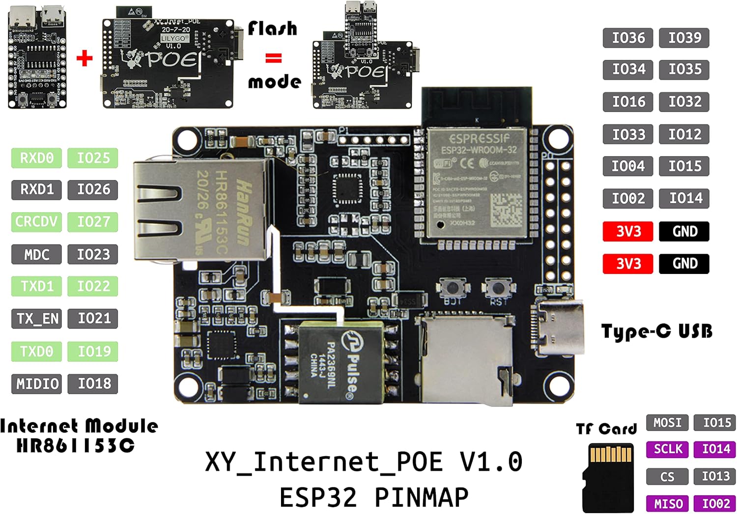
A detailed diagram illustrating the pin assignments and functions of the ESP32 module on the board, including GPIOs, power, and communication lines.

This graphic summarizes the main technical specifications, including MCU type, flash memory, wireless connectivity, and PoE input voltage range.

A diagram providing the physical dimensions of both the main T-Internet-POE board and the separate downloader module in millimeters.
3. Setup
To begin using your LILYGO T-Internet-POE board, follow these setup steps:
- Connect the Downloader Module: The T-Internet-POE board requires the included downloader expansion board for programming. Carefully align and connect the downloader module to the main board's dedicated programming header.
- Power Supply: The board can be powered via the USB-C port on the downloader module or through Power over Ethernet (PoE) via the Ethernet port. Ensure your power source meets the specified voltage requirements (2.7V ~ 10.1V for PoE PD).
- Driver Installation: If connecting to a computer for programming, you may need to install the appropriate USB-to-serial drivers (e.g., CH340C) for your operating system.
- Development Environment Setup: For programming the ESP32, set up your preferred development environment, such as Arduino IDE or ESP-IDF. Refer to the official LILYGO GitHub repository for detailed setup guides and example code: github.com/Xinyuan-LilyGO/LilyGO-T-ETH-POE.
4. Operating Instructions
Once set up, the LILYGO T-Internet-POE board can be operated for various applications:
- Programming: Use the connected downloader module and your development environment to upload firmware to the ESP32. The module provides a USB serial console for communication during development.
- Ethernet Connectivity: Connect an Ethernet cable to the RJ45 port. The LAN8720A chip handles the physical layer communication, allowing your ESP32 application to utilize wired network access.
- Wi-Fi and Bluetooth: The ESP32-WROOM module supports 802.11n Wi-Fi and BLE V4.2, enabling wireless communication for your projects.
- GPIO Usage: Utilize the available GPIO pins for connecting sensors, actuators, and other peripheral components. Refer to the pinout diagram (Figure 2.5) for specific pin functions.
- TF Card Support: The board includes a TF card slot for external storage, useful for data logging or storing larger files.
5. Maintenance
Proper handling and maintenance will ensure the longevity of your LILYGO T-Internet-POE board:
- Electrostatic Discharge (ESD) Protection: Electronic components are sensitive to ESD. Always handle the board by its edges and use anti-static precautions (e.g., an ESD wrist strap) when working with it.
- Do Not Remove Yellow Sticker: There is a yellow reminder sticker on the board. Do not remove this sticker. It is present to protect the underlying chip from static electricity and potential damage if touched directly, especially when the board is powered.
- Cleanliness: Keep the board free from dust, dirt, and moisture. Use a soft, dry brush or compressed air for cleaning. Avoid using liquids.
- Storage: Store the board in an anti-static bag in a dry, cool environment when not in use.

This image visually reinforces the importance of ESD protection and the critical instruction to not remove the yellow protective sticker from the board.
6. Troubleshooting
If you encounter issues with your LILYGO T-Internet-POE board, consider the following:
- Programming Errors: Ensure the downloader module is correctly attached and that the correct COM port and board settings are selected in your IDE. Verify USB-to-serial drivers are installed.
- No Power: Check USB-C cable connection or PoE source. Ensure the power supply meets the board's requirements.
- Ethernet Not Working: Verify the Ethernet cable connection. Check your network configuration in the ESP32 firmware. Ensure your PoE injector/switch is providing power correctly if using PoE.
- Board Not Responding: Try pressing the RST (Reset) button. If issues persist, re-flash the firmware.
- Static Discharge Damage: If the board was handled without ESD precautions, internal components might be damaged. This is often irreversible.
For more in-depth troubleshooting and community support, visit the official LILYGO GitHub repository: github.com/Xinyuan-LilyGO/LilyGO-T-ETH-POE.
7. Specifications
| Feature | Specification |
|---|---|
| MCU | ESP32-WROOM |
| Flash Memory | 4 MB |
| Ethernet Chip | LAN8720A |
| Wireless Connectivity | Wi-Fi: 802.11 b/g/n/, BLE V4.2 |
| PoE PD Voltage Input Range | 2.7V ~ 10.1V (Si3404) |
| USB Interface | Type-C (on downloader module) |
| Onboard Buttons | RST + BOOT |
| TF Card Support | Yes |
| Dimensions (Main Board) | Approx. 70mm x 52.3mm |
| Weight | Approx. 1.12 ounces (31.75 grams) |
8. Warranty and Support
LILYGO products are designed for reliability and performance. For technical support, documentation, and community resources, please refer to the official LILYGO GitHub repository:
github.com/Xinyuan-LilyGO/LilyGO-T-ETH-POE
Regarding returns, the product typically has a 30-day return policy for refund or replacement, as per standard retail terms. Please refer to your purchase platform's specific return policy for detailed information.