Introduction
This manual provides instructions for the ciciglow RF Remote Control Kit, which includes a DC6V-36V receiver and a DC5V-24V transmitter. This kit is designed for various wireless control applications, offering stable signal transmission and a wide operating range.
The kit is suitable for controlling switches, lamps, relays, and other small devices in home automation and security systems.
Package Contents
- 1 x RF Receiver Module (DC6V-36V)
- 1 x RF Transmitter Module (DC5V-24V)
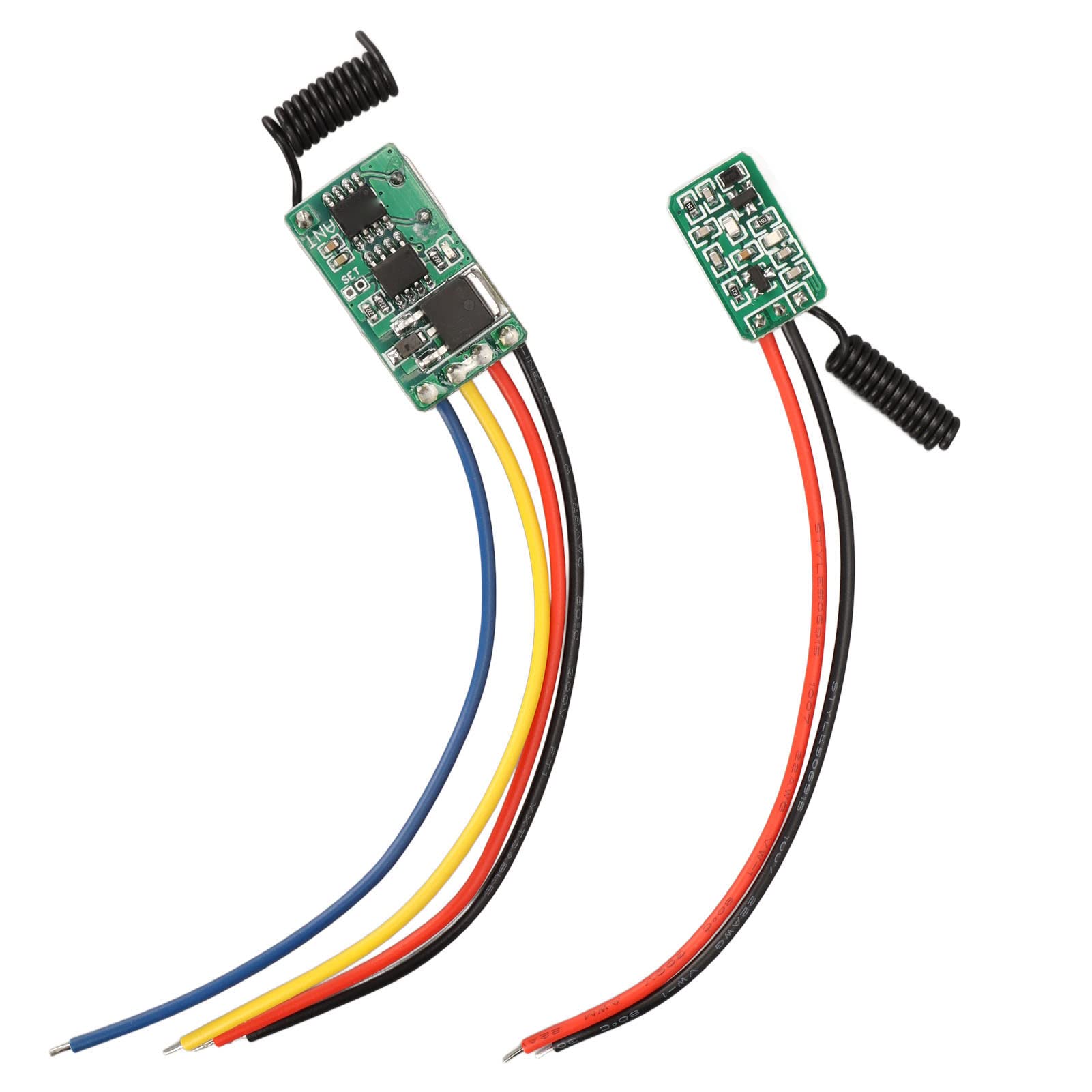
Figure 1: Contents of the RF Remote Control Kit, including the receiver and transmitter modules.
Specifications
Receiver Module
- Operating Voltage: DC 6V-36V
- Maximum Load: 5A (Note: If controlling a motor, load should be less than 3A)
- Operating Frequency: 433 MHz
- Frequency Deviation: ±0.2 MHz
- Operating Temperature: -20°C to 80°C
- Reception Sensitivity: ≥ -109 dBm
- Modulation Type: Amplitude Modulation (AM)
- Encoding Type: Learning point for adding transmitters
- Output State: Momentary, Toggle, Latched (adjustable by connecting different points)
Transmitter Module
- Operating Voltage: DC 5V-24V
- Modulation Mode: ASK
- Operating Frequency: 433 MHz
- Operating Current: 8-10 mA
- Transmission Power: 21 mW
- Encoding Type: Learning code (EV1527)
- Transmission Distance: Approximately 10-100 meters (without obstacles)
- Reception Sensitivity: 108 dBm

Figure 2: Detailed view of the receiver and transmitter modules.
Setup and Wiring
Before connecting, ensure all power sources are disconnected. Incorrect wiring can damage the modules.
Receiver Module Wiring
The receiver module typically has connections for VCC (power input), GND (ground), and OUT (output). Refer to the markings on the PCB for precise connections.
- VCC: Connect to a DC power source between 6V and 36V.
- GND: Connect to the ground of the power source.
- OUT: This is the control output. Its state (ON/OFF) is controlled by the transmitter. The blue output wire from the receiver is open circuit when OFF and tied to ground when ON.
Transmitter Module Wiring
The transmitter module requires a DC power input to operate. It does not have physical buttons; activation is achieved by applying power.
- VCC: Connect to a DC power source between 5V and 24V.
- GND: Connect to the ground of the power source.
To activate the transmitter, connect a button (e.g., a doorbell button) in series with the 5V to 24V power supply to the transmitter board. When the button is pressed, power is supplied, and the signal is transmitted.
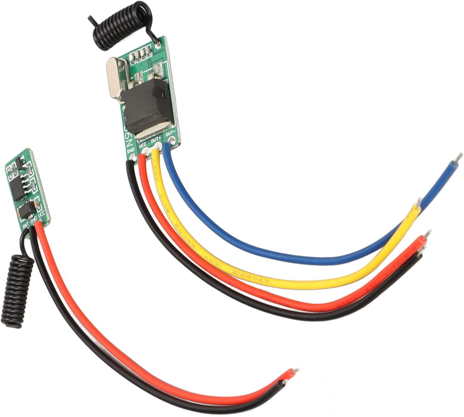
Figure 3: Receiver module with wiring points labeled VCC, GND, and OUT.

Figure 4: Transmitter module with power input connections.
Operating Modes and Programming
The receiver module supports three operating modes: Momentary, Toggle, and Latched. These modes determine how the receiver's output behaves when it receives a signal from the transmitter.
Understanding Operating Modes
- Momentary Mode: The receiver's output is ON only while the transmitter is actively sending a signal (i.e., while the transmitter is powered ON). The output turns OFF when the transmitter stops sending a signal. This is suitable for applications like doorbells or gate openers.
- Toggle Mode: Each time the receiver receives a signal from the transmitter, its output state switches. If the output is OFF, it turns ON. If it's ON, it turns OFF. This is suitable for applications like turning a light ON/OFF.
- Latched Mode: One transmitter signal turns the output ON, and another distinct transmitter signal (or a different button on the same transmitter, if supported) turns it OFF. The provided kit description suggests this mode is adjustable by connecting different points, but specific details are not provided for this kit. For this kit, it's generally recommended to use Momentary or Toggle modes.
Programming the Receiver (Learning Process)
The receiver module does not have a physical "learning button" as commonly found. Instead, it uses a pair of silvered pads labeled "SET" on the circuit board. These pads must be momentarily shorted together to initiate the learning process and select the operating mode.
Recommended Setup for Programming: Use separate 9V batteries with connectors to power the transmitter and receiver modules during programming. This allows for easier manipulation without being constrained by the final installation.
- Power the Receiver: Connect a DC power source (e.g., 9V battery) to the receiver module's VCC and GND terminals.
- Initiate Learning Mode: Momentarily short the "SET" pads on the receiver's circuit board using a small screwdriver, wire, or tweezers.
- Select Operating Mode: Observe the red LED on the receiver.
- One blink: Toggle Mode
- Two blinks: Momentary Mode
- Three blinks: Latched Mode (Note: Functionality for this mode may vary or require specific wiring not detailed for this kit.)
- Bind Transmitter: Immediately after releasing the "SET" pads, apply power to the transmitter module (e.g., by pressing the button connected to its power supply). The red LED on the receiver should blink again to indicate successful pairing. If it does not blink, repeat step 2 by shorting the SET pads for approximately 2 seconds, then operate the transmitter again.
- Test: After successful programming, test the functionality by applying and removing power to the transmitter. For Momentary mode, the receiver's output LED should turn ON when the transmitter is powered and OFF when power is removed. For Toggle mode, each power application to the transmitter should switch the receiver's output state.
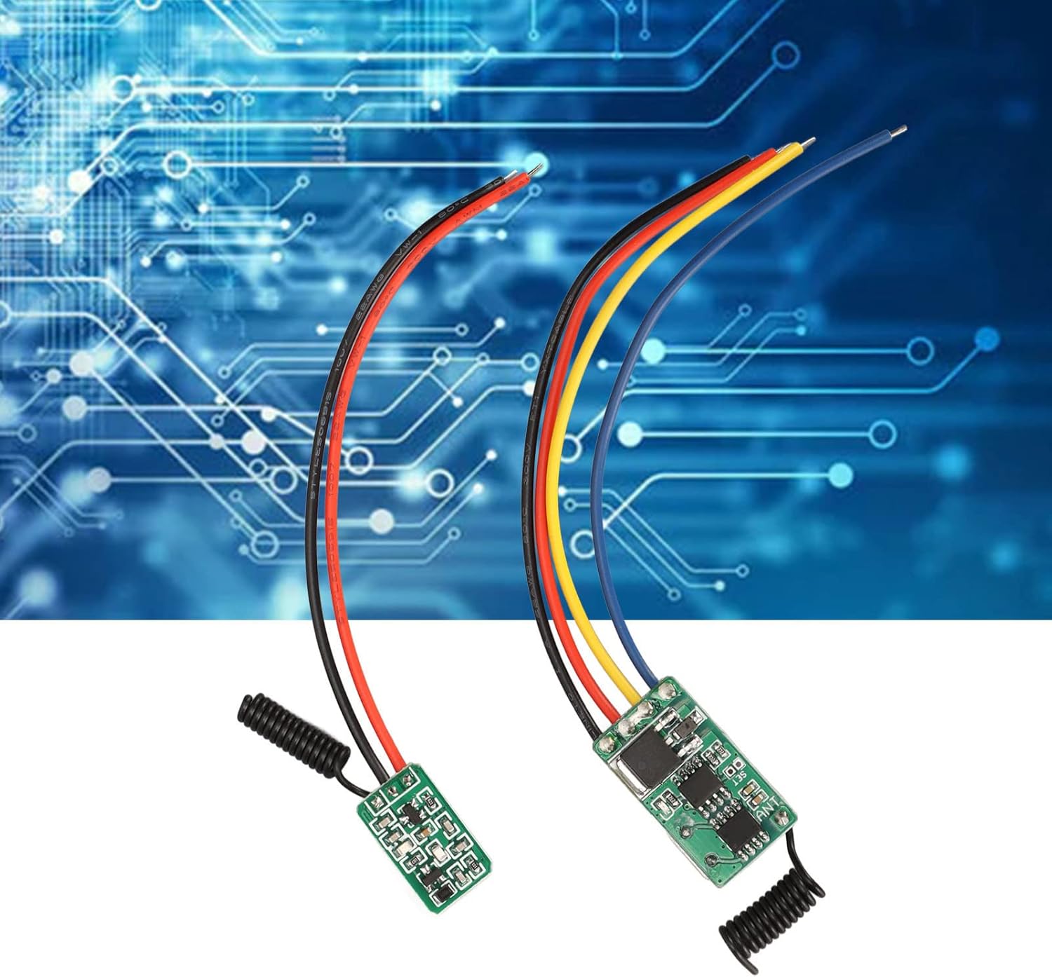
Figure 5: Receiver module circuit board, indicating the 'SET' pads for mode selection and programming.
Typical Applications
This RF remote control kit is versatile and can be integrated into various systems:
- Wireless control for switches and lamps.
- Remote activation of relays.
- Integration into circuit boards for custom projects.
- Remote power switching for small appliances.
- Home wireless control systems.
- Security industry applications.
- Battery ON/OFF control for small devices.
- Garage door openers (as demonstrated in a user review).
Troubleshooting
- No Response from Receiver:
- Ensure both receiver and transmitter are correctly powered within their specified voltage ranges.
- Verify that the transmitter is actively sending a signal (i.e., receiving power when activated).
- Confirm that the receiver and transmitter are successfully paired. Repeat the programming steps if necessary.
- Check for excessive distance or significant obstacles between the transmitter and receiver. The maximum range is 100 meters without obstacles, which will be reduced by walls and other structures.
- Inspect wiring for loose connections or incorrect polarity.
- Incorrect Operating Mode:
- If the receiver is not behaving as expected (e.g., toggling instead of momentary), repeat the programming steps carefully, ensuring you release the "SET" pads after the correct number of LED blinks for your desired mode.
- Poor Signal Quality / Intermittent Operation:
- Ensure the antennas on both modules are not obstructed or damaged.
- Minimize sources of RF interference in the vicinity.
- Consider relocating the modules to improve line-of-sight or reduce signal path obstructions.
- Physical Damage / Poor Soldering:
- Visually inspect the modules for any signs of damage or poor soldering, especially at wire connection points. If issues are found, professional repair or replacement may be necessary.
Maintenance
The ciciglow RF Remote Control Kit requires minimal maintenance. Follow these guidelines to ensure optimal performance and longevity:
- Keep Dry: Protect the modules from moisture and humidity, which can cause short circuits and corrosion.
- Clean Gently: If cleaning is necessary, use a soft, dry cloth. Avoid using harsh chemicals or abrasive materials.
- Temperature Control: Operate the modules within the specified temperature range of -20°C to 80°C. Avoid extreme heat or cold.
- Secure Connections: Periodically check all wired connections to ensure they are secure and free from corrosion.
- Antenna Care: Ensure the coiled antennas are not bent, broken, or obstructed, as this can affect signal range and reliability.
Warranty and Support
Information regarding specific warranty terms is not provided in the product details. For warranty claims or technical support, please contact your retailer or the manufacturer, ciciglow, directly. Please have your product model number (B0BHX3YJCK) and purchase date available when contacting support.
Manufacturer: ciciglow
Country of Origin: China