
1. Introduction
The STLINK-V3MINIE is a compact, stand-alone in-circuit debugger and programmer designed for STM32 microcontrollers. It offers portability and ease of use, featuring onboard JTAG/SWD interfaces for communication with STM32 microcontrollers. Additionally, it provides a virtual COM port, enabling the host PC to communicate with the target microcontroller via a UART connection.
This manual provides detailed instructions for setting up, operating, and maintaining your STLINK-V3MINIE, ensuring optimal performance and longevity.

Image: The STLINK-V3MINIE unit, highlighting its function as an STM32 debugger and programmer.
2. Features At A Glance
The STLINK-V3MINIE offers a robust set of features for efficient debugging and programming:
- Compact Design: Tiny 15 mm x 42 mm stand-alone debugging and programming probe.
- Power Supply: Self-powered through a USB Type-C connector.
- High-Speed Interface: USB 2.0 high-speed interface for fast data transfer.
- Firmware Updatable: Probe firmware can be updated conveniently via USB.
- Flash Programming: Supports drag-and-drop Flash programming of binary files.
- LED Indicators: Two color LEDs for communication and power status.
- JTAG Communication: Supports up to 21 MHz.
- SWD/SWV Communication: Supports Serial Wire Debug (SWD) and Serial Wire Viewer (SWV) up to 24 MHz.
- Virtual COM Port (VCP): Up to 15 Mbps.
- Application Voltage Support: Compatible with 1.65 to 3.60 V applications.
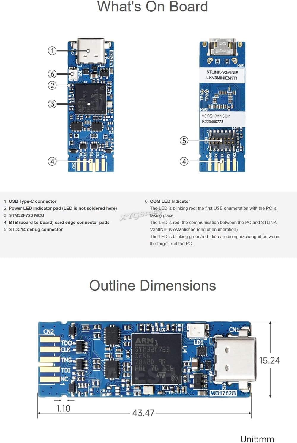
Image: A visual summary of the key features of the STLINK-V3MINIE debugger.
3. Package Contents
Upon opening your STLINK-V3MINIE package, you should find the following items:
- STLINK-V3MINIE unit x 1
- STLINK-V3MINI Adapter x 1
- STDC14 flat cable (1.27 mm pitch) x 1
- USB Type-C cable x 1
- Dupont wires x 1 set

Image: All components included in the STLINK-V3MINIE package, including the main unit, adapter, and various cables.
4. Setup
4.1 Interface Introduction
Familiarize yourself with the various interfaces on the STLINK-V3MINIE unit:
- USB Type-C Connector (CN1): For power and communication with the host PC.
- 2.0 mm pitch pads (CN2): For board-to-board (BTB) card edge connector.
- STDC14 Debug Connector: Used with the STDC14 flat cable for connecting to the target.
- LED Indicators: Two LEDs (Power and COM) indicate device status.

Image: Detailed view of the STLINK-V3MINIE, pointing out the USB Type-C connector and 2.0 mm pitch pads.
4.2 What's On Board
A closer look at the components and indicators on the STLINK-V3MINIE:
- USB Type-C connector
- Power LED indicator pad (LED not soldered here)
- STM32F723 MCU
- BTB (board-to-board) card edge connector pads
- STDC14 debug connector
- COM LED indicator:
- The LED is blinking red: the first USB enumeration with the PC is taking place.
- The LED is red: the communication between the PC and STLINK-V3MINIE is established (end of enumeration).
- The LED is blinking green/red: data are being exchanged between the target and the PC.
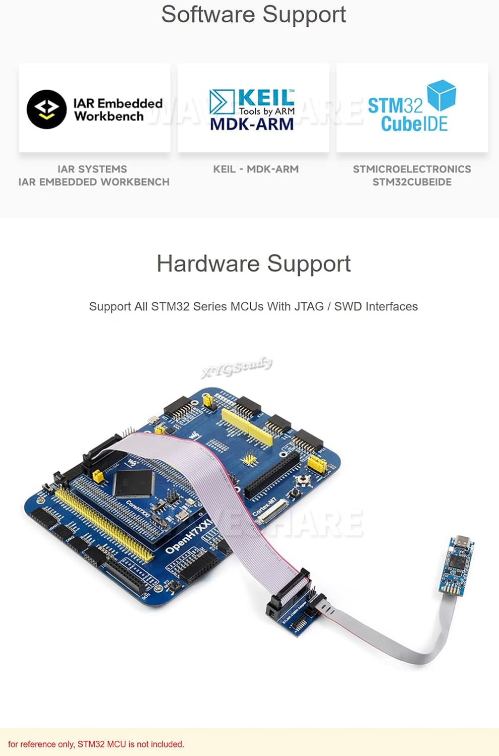
Image: Annotated diagram showing the various components and indicators on the STLINK-V3MINIE board.
5. Operating Instructions
5.1 Connection Examples
The STLINK-V3MINIE can be connected to your target STM32 application in a few ways:
- Direct Connection: Connect the STLINK-V3MINIE directly to the JTAG / SWD interfaces of the STM32 target application via the STDC14 connector.
- Using an Adapter: Connect to the target application using the provided STLINK-V3MINI Adapter for more flexible connections.

Image: Visual examples demonstrating direct and adapter-based connection methods for the STLINK-V3MINIE.
5.2 Software Support
The STLINK-V3MINIE is compatible with leading development environments for STM32 microcontrollers:
- IAR Embedded Workbench
- KEIL MDK-ARM
- STM32CubeIDE
Ensure you have the latest drivers and software installed for seamless operation.

Image: Logos of supported software development environments: IAR Embedded Workbench, KEIL MDK-ARM, and STM32CubeIDE.
5.3 Hardware Support
The STLINK-V3MINIE supports all STM32 series MCUs that feature JTAG / SWD interfaces. This broad compatibility makes it a versatile tool for various STM32 development projects.

Image: An example setup showing the STLINK-V3MINIE connected to a development board, illustrating its hardware compatibility.
5.4 STLINK Series Selection Guide
For comparison with other STLINK series debuggers, refer to the table below:
| ITEM | V3MINIE | V3SET | V2 |
|---|---|---|---|
| JTAG/SWD APPLICATION VOLTAGE | 1.65V~3.6V | 3V~3.6V | 1.65V~3.6V |
| SWIM APPLICATION VOLTAGE | N/A | 1.65V~5.5V | 1.65V~5.5V |
| SWV SUPPORT | YES | YES | YES |
| DEBUG INTERFACE | multi | multi | 2 |
| LED INDICATOR | two colors | two colors | two colors |

Image: A table comparing the features of STLINK-V3MINIE with other STLINK series models (V3SET, V2).
6. Maintenance
To ensure the longevity and proper functioning of your STLINK-V3MINIE, follow these maintenance guidelines:
- Keep the device clean and free from dust and debris. Use a soft, dry cloth for cleaning.
- Avoid exposing the device to extreme temperatures, humidity, or direct sunlight.
- Handle the connectors and cables with care to prevent damage.
- Store the device in a safe, dry place when not in use.
- Regularly check for firmware updates to ensure optimal performance and compatibility.
7. Troubleshooting
If you encounter issues with your STLINK-V3MINIE, consider the following common troubleshooting steps:
- Device Not Recognized: Ensure the USB Type-C cable is securely connected to both the STLINK-V3MINIE and your PC. Try a different USB port or cable. Verify that the necessary drivers are installed on your computer.
- Connection Errors: Check all cable connections between the STLINK-V3MINIE and the target microcontroller. Ensure the target board is powered correctly. Verify that the target voltage is within the supported range (1.65V-3.6V).
- Programming/Debugging Failures: Confirm that your development environment (IAR, KEIL, STM32CubeIDE) is correctly configured for the target microcontroller and STLINK-V3MINIE. Ensure the firmware on the STLINK-V3MINIE is up to date.
- LED Indicators: Refer to the "What's On Board" section for the meaning of the COM LED indicator to diagnose communication issues.
If problems persist, consult the official STMicroelectronics documentation or contact customer support.
8. Specifications
Detailed technical specifications for the STLINK-V3MINIE:
- Model Name: STLINK-V3MINIE Stand-Alone
- Part Number: STLINK-V3MINIE
- Processor: STM32F723 MCU
- Connectivity: USB Type-C, JTAG, SWD, UART (Virtual COM Port)
- JTAG Communication Speed: Up to 21 MHz
- SWD/SWV Communication Speed: Up to 24 MHz
- Virtual COM Port Speed: Up to 15 Mbps
- Application Voltage: 1.65V to 3.60V
- Dimensions: Approximately 43.47 mm (length) x 15.24 mm (width) x 1.10 mm (thickness of PCB)
- Weight: Approximately 3.45 ounces
- Color: Blue
Image: Diagram illustrating the outline dimensions of the STLINK-V3MINIE unit in millimeters.
9. Warranty and Support
This product is covered by a standard manufacturer's warranty. Please refer to the product packaging or the manufacturer's official website for specific warranty terms and conditions.
For technical support, additional resources, or inquiries, please contact XYGStudy customer service via Amazon message. We are committed to providing assistance and ensuring your satisfaction with the STLINK-V3MINIE.