
MULTICOMP PRO MP760606
MULTICOMP PRO Digital Clamp Multimeter User Manual
Model: MP760606
Brand: MULTICOMP PRO
1. Introduction
Thank you for choosing the MULTICOMP PRO Digital Clamp Multimeter, Model MP760606. This 4000-count, 400A digital clamp meter is designed for safe and accurate measurement of AC current, AC/DC voltage, resistance, continuity, diode, frequency, and temperature. It is an ideal tool for professional electricians, technicians, and DIY enthusiasts.
Please read this manual thoroughly before operating the device to ensure proper use and to prevent potential hazards.
2. Safety Information
Always adhere to basic safety precautions when using electrical test equipment to reduce the risk of fire, electric shock, or personal injury.
- Do not exceed the maximum input limits for any function.
- Use extreme caution when working with voltages above 30V AC RMS, 42V peak, or 60V DC. These voltages pose a shock hazard.
- Before measuring current, ensure the circuit is de-energized and the clamp jaws are properly closed around a single conductor.
- Always disconnect the test leads from the circuit before changing functions or ranges.
- Do not use the meter if it appears damaged or if the insulation on the test leads is compromised.
- Replace the battery immediately when the low battery indicator appears.
- Refer to the CAT ratings (CAT III 300V, CAT II 600V) for appropriate measurement environments.
3. Product Features
- 4000-count digital display.
- Measures AC Current up to 400A.
- Measures AC/DC Voltage.
- Resistance, Continuity, Diode, and Frequency measurement.
- Temperature measurement.
- Non-Contact Voltage (NCV) detection.
- Data Hold, MAX/MIN function.
- True RMS for accurate AC measurements.
- Compact and lightweight design (Weight: 248g).
4. Package Contents
Verify that all items are present and undamaged upon opening the package:
- MULTICOMP PRO Digital Clamp Multimeter (MP760606)
- Test Leads (Red and Black)
- Temperature Probe
- User Manual
- Carrying Pouch (Optional, depending on package)
5. Product Overview
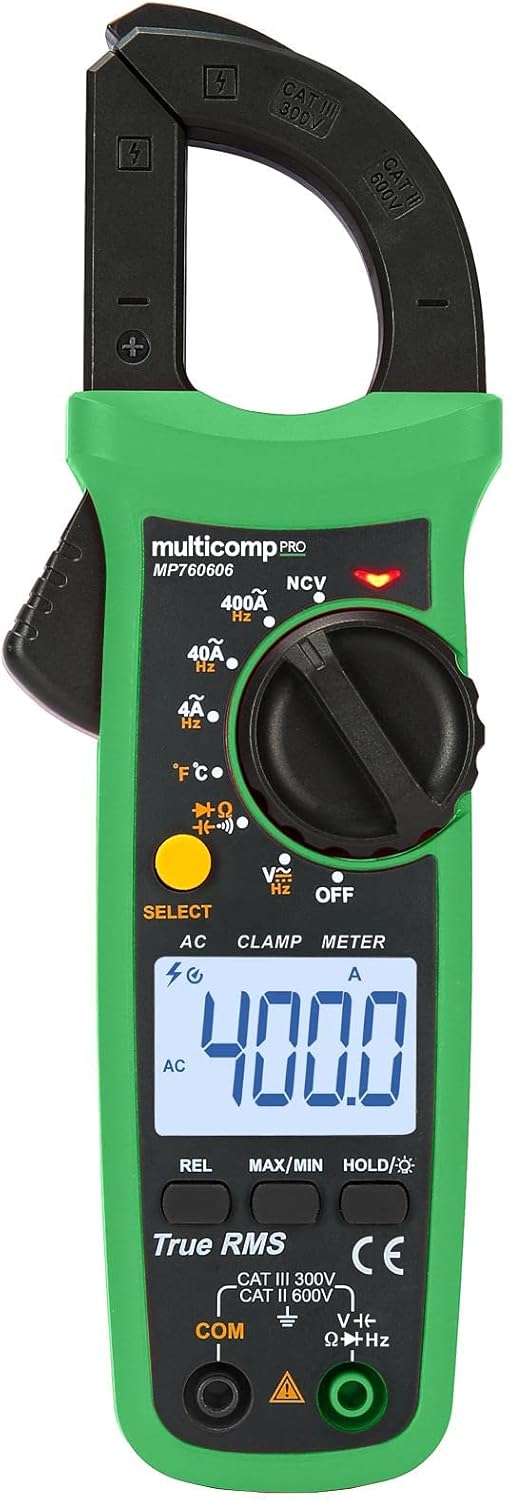
Figure 1: Front view of the MULTICOMP PRO Digital Clamp Multimeter MP760606, showing the clamp jaws, rotary dial, LCD display, function buttons, and input jacks.

Figure 2: Angled view of the MULTICOMP PRO Digital Clamp Multimeter MP760606, highlighting its compact form factor.
5.1. Controls and Indicators
- Clamp Jaws: For non-contact AC current measurement.
- Rotary Dial: Selects measurement functions (ACV, DCV, Ohms, Continuity, Diode, Hz, Temperature, ACA, NCV, OFF).
- LCD Display: Shows measurement readings, units, and function indicators.
- Function Buttons:
- SELECT: Toggles between functions within a single rotary dial position (e.g., ACV/DCV, Ohms/Continuity/Diode).
- REL: Relative measurement mode.
- MAX/MIN: Records maximum and minimum readings.
- HOLD/★: Data Hold function; long press for backlight.
- Input Jacks:
- COM: Common (negative) input for all measurements except current.
- VΩHz: Positive input for Voltage, Resistance, Frequency, Diode, and Continuity measurements.
- NCV Sensor: Detects live AC voltage without contact.
6. Setup
6.1. Battery Installation
The meter is powered by batteries (not included as per specifications). To install or replace batteries:
- Ensure the meter is turned OFF.
- Locate the battery compartment cover on the back of the meter.
- Unscrew the retaining screw(s) and remove the cover.
- Insert new batteries, observing correct polarity (+ and -).
- Replace the battery compartment cover and secure it with the screw(s).
Note: The meter uses a battery power source. Refer to the battery type specified in the specifications section (typically AAA or 9V, though not explicitly stated in the provided data).
7. Operating Instructions
Before taking any measurements, ensure the test leads are in good condition and properly connected to the meter.
7.1. AC Current Measurement (Clamp)
- Turn the rotary dial to the "400A" or "40A" AC current range.
- Press the clamp trigger to open the jaws.
- Place the jaws around a single conductor (not a power cord with multiple wires).
- Release the trigger to close the jaws securely around the conductor.
- Read the AC current value on the LCD display.
7.2. AC/DC Voltage Measurement
- Insert the red test lead into the VΩHz input jack and the black test lead into the COM input jack.
- Turn the rotary dial to the "V~" (AC Voltage) or "V—" (DC Voltage) position. Use the SELECT button to toggle if needed.
- Connect the test leads in parallel to the circuit or component to be measured.
- Read the voltage value on the LCD display.
7.3. Resistance, Continuity, Diode Measurement
- Insert the red test lead into the VΩHz input jack and the black test lead into the COM input jack.
- Turn the rotary dial to the "ΩΩΩ" position.
- Use the SELECT button to cycle through Resistance (Ω), Continuity (♫), and Diode (→|•) functions.
- For Resistance: Connect leads across the component.
- For Continuity: Connect leads across the circuit. A beep indicates continuity.
- For Diode: Connect red lead to anode, black to cathode.
- Read the value on the LCD display.
7.4. Frequency Measurement (Hz)
- Insert the red test lead into the VΩHz input jack and the black test lead into the COM input jack.
- Turn the rotary dial to the "Hz" position.
- Connect the test leads in parallel to the circuit where frequency is to be measured.
- Read the frequency value on the LCD display.
7.5. Temperature Measurement (℃/℉)
- Turn the rotary dial to the "℃/℉" position.
- Insert the temperature probe into the input jacks, observing polarity.
- Place the tip of the probe on the object or area whose temperature is to be measured.
- Read the temperature value on the LCD display. Use the SELECT button to switch between Celsius and Fahrenheit.
7.6. Non-Contact Voltage (NCV) Detection
- Turn the rotary dial to the "NCV" position.
- Move the NCV sensor (located at the top of the meter) close to the conductor or outlet.
- The meter will emit an audible beep and/or flash an LED indicator if AC voltage is detected.
8. Maintenance
8.1. Cleaning
Wipe the case with a damp cloth and mild detergent. Do not use abrasives or solvents. Keep the input terminals free of dirt or debris.
8.2. Battery Replacement
When the low battery indicator appears on the display, replace the batteries as described in the "Battery Installation" section (Section 6.1). Always use the specified battery type.
8.3. Fuse Replacement (If Applicable)
This clamp meter typically does not have user-replaceable fuses for current measurement via the clamp. For voltage and other functions, if a fuse is present and needs replacement, refer to the specific instructions in the full product manual or contact customer support. Always use a fuse of the specified type and rating.
9. Troubleshooting
| Problem | Possible Cause | Solution |
|---|---|---|
| Meter does not power on. | Dead or incorrectly installed batteries. | Check battery polarity; replace batteries. |
| "OL" (Overload) displayed. | Measurement exceeds selected range or meter's maximum capacity. | Select a higher range or ensure measurement is within meter's limits. |
| Inaccurate readings. | Low battery; poor test lead connection; external interference. | Replace batteries; ensure leads are firmly connected; move away from strong electromagnetic fields. |
| No NCV detection. | No AC voltage present; NCV sensor not close enough. | Verify power is present; ensure sensor is directly over the live wire. |
10. Specifications
| Parameter | Value |
|---|---|
| Display | 4000 Counts |
| AC Current Range | 40A / 400A |
| AC/DC Voltage | Yes |
| Resistance | Yes |
| Continuity | Yes |
| Diode Test | Yes |
| Frequency | Yes |
| Temperature | Yes |
| Non-Contact Voltage (NCV) | Yes |
| True RMS | Yes |
| Power Source | Battery |
| Weight | 248 g |
| Manufacturer | MULTICOMP PRO |
| Model Number | MP760606 |
| Safety Rating | CAT III 300V, CAT II 600V |
11. Warranty and Support
MULTICOMP PRO products are designed for reliability and performance. For warranty information, technical support, or service inquiries, please refer to the warranty card included with your product or visit the official MULTICOMP PRO website. Keep your purchase receipt as proof of purchase for warranty claims.
For further assistance, you may contact your local distributor or the point of purchase.
Related documentsMP760606

Ask a question about this manual
Ask about setup, troubleshooting, compatibility, parts, safety, or missing instructions. Manuals+ will review the question and use this page’s manual context to help answer it.