1. Introduction
The Greluma STC-3008 is a versatile digital temperature controller designed for precise temperature regulation in various applications. It features a dual display for simultaneous monitoring of two temperatures, dual NTC probe sensors for accuracy, and supports both heating and cooling modes. This manual provides detailed instructions for the safe and effective use of your STC-3008 controller.
2. Safety Information
WARNING: Electrical shock hazard. Installation and wiring should only be performed by qualified personnel. Disconnect power before installation or maintenance.
- Ensure the power supply voltage matches the controller's requirements (AC 110V-220V).
- Strictly distinguish between relay, sensor, and power interfaces during wiring.
- Maintain proper distance between sensor down-lead and power wires to prevent interference.
- Do not operate the device in environments with excessive moisture, dust, or corrosive gases.
- The ABS flame-retardant plastic shell provides safety, but proper ventilation should still be ensured.
3. Product Overview
3.1 Key Features
- Dual screen dual digital display for clear temperature readings.
- Dual NTC probes for accurate temperature measurement (accuracy: ±1°C from -50°C to 70°C).
- Adjustable dual temperature control for independent heating/cooling outputs.
- Automatic switching between heating and cooling modes.
- Programmable start/stop temperatures and delayed start function.
- Low/high temperature alarm for enhanced safety.
- Durable ABS flame-retardant plastic shell.

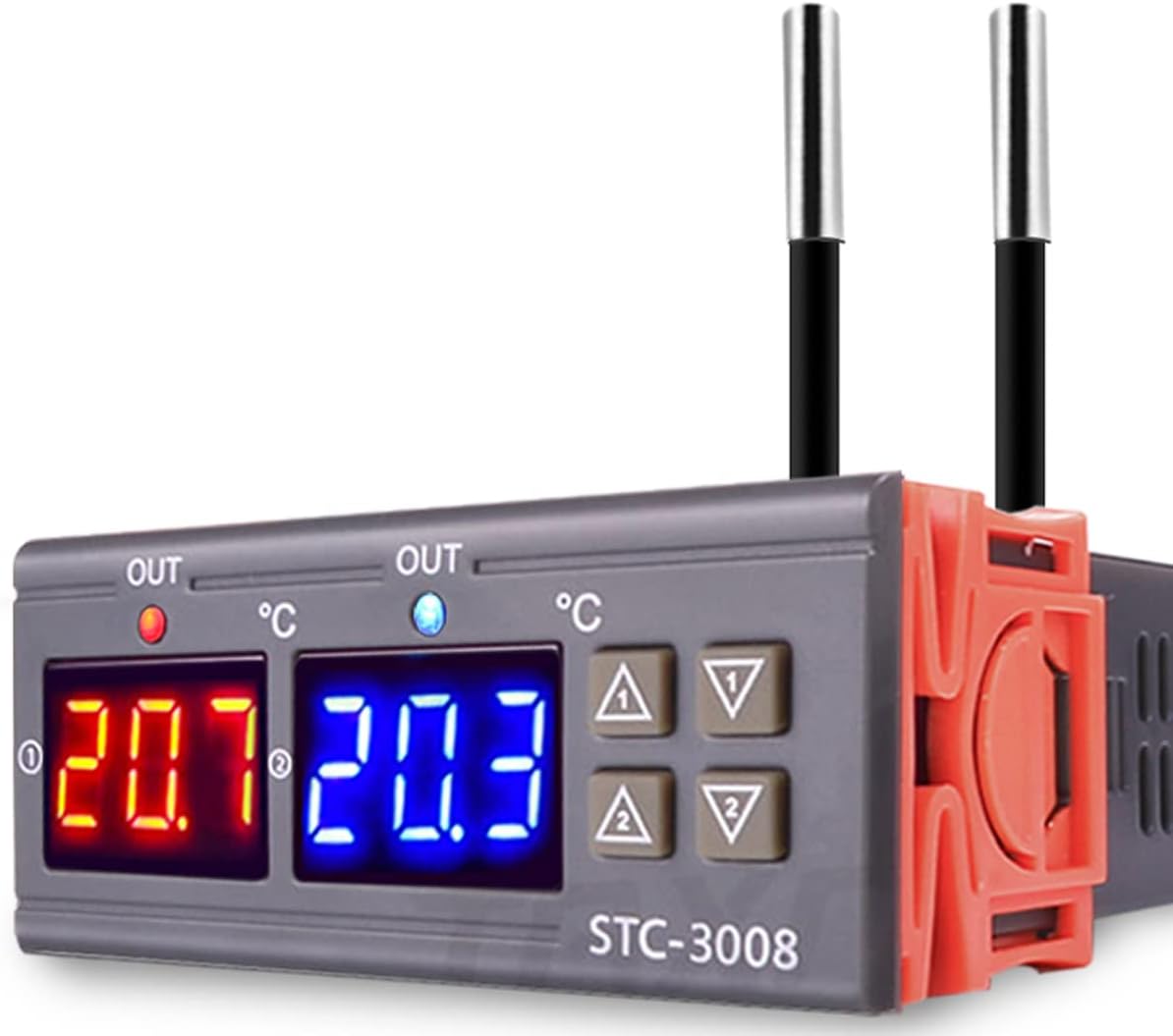
3.2 Component Identification

The STC-3008 features a robust design with high-quality internal components for reliable performance. External features include:
- Dual Digital Displays: Two separate displays show measured temperatures for each channel.
- Control Buttons: Up and Down arrows for each channel (NO.1 and NO.2) for setting parameters.
- NTC Probe Sensors: Two external NTC sensors for accurate temperature detection.
- Terminal Blocks: Secure screw terminals for power input and load outputs.

4. Specifications
| Parameter | Value |
|---|---|
| Model | STC-3008 |
| Power Supply | AC 110V-220V |
| Output Relay Contact Capacity | 10A max |
| Temperature Control Range | -55°C to 100°C |
| Measurement Accuracy | ±0.1°C |
| Temperature Control Accuracy | ±1°C |
| Sensor Type | NTC Probe (10K/3435) |
| Probe Length | 1 meter (approx. 3.28 feet) |
| Shell Material | ABS Flame Retardant Plastic |
| Dimensions (L x W x H) | Approx. 86mm x 75mm x 35mm (3.39" x 2.95" x 1.38") |
| Mounting Hole Size | Approx. 70mm x 27mm (2.76" x 1.06") |
| Item Weight | 0.11 Kilograms |

5. Installation and Wiring
Proper wiring is critical for the safe and correct operation of the STC-3008. Refer to the diagrams below and ensure all connections are secure.
5.1 Wiring Diagram 1: Independent Power Supply for Load

In this configuration, the controller's power supply is separate from the power supply for the connected heating or cooling load. This is suitable for applications where the load requires a different voltage or current than the controller's input.
5.2 Wiring Diagram 2: Same Power Supply for Load

This diagram illustrates connecting the STC-3008 where both the controller and the heating/cooling load share a common power source. Ensure the total current draw does not exceed the controller's relay capacity (10A max).
5.3 General Wiring Notes
- Connect the NTC probes to the designated sensor terminals.
- Ensure all wire connections are tight and secure to prevent loose contacts and potential hazards.
- Verify correct polarity for power connections.
- Mount the controller in a location that is protected from moisture and excessive heat.
6. Operating Instructions
The STC-3008 allows for independent control of two temperature channels. Each channel (NO.1 and NO.2) has its own set of parameters.
6.1 Setting Start and Stop Temperatures
To set the desired temperature range for each channel:
- Power On: Ensure the controller is powered on. The current measured temperatures will be displayed.
- Enter Setting Mode: Press and hold the 'Up' button for NO.1 (or NO.2) for approximately 3 seconds until the display starts flashing. This is the Start Temperature setting.
- Adjust Start Temperature: Use the 'Up' or 'Down' buttons for that channel to adjust the desired start temperature.
- Set Stop Temperature: Press and hold the 'Down' button for NO.1 (or NO.2) for approximately 3 seconds until the display starts flashing. This is the Stop Temperature setting.
- Adjust Stop Temperature: Use the 'Up' or 'Down' buttons for that channel to adjust the desired stop temperature.
- Save Settings: The settings will automatically save after a few seconds of inactivity, or you can briefly press the 'Power' button (if available, otherwise wait for auto-save).
Note: For heating mode, the Start Temperature should be lower than the Stop Temperature. For cooling mode, the Start Temperature should be higher than the Stop Temperature.
6.2 Delayed Start Time (Compressor Protection)
This function protects refrigerating equipment by delaying the compressor start after power-on or a short cycle. The setting procedure is similar to temperature settings, typically accessed by holding a specific button combination or cycling through parameters.
- Consult the specific parameter codes (P-codes) usually printed on a label on the device or included in a quick-start guide for advanced settings like delayed start time or temperature calibration.
- A common method involves holding a 'Set' button (if present) and then using 'Up'/'Down' to navigate through P-codes (e.g., P0, P1, P2...).
6.3 Temperature Calibration
If the measured temperature deviates from a known accurate reference, you can calibrate the sensor. This is typically done via a parameter setting (e.g., P4 or P5) where you can add or subtract an offset value.
7. Maintenance
- Cleaning: Regularly wipe the controller's surface with a soft, dry cloth. Do not use abrasive cleaners or solvents.
- Probe Care: Ensure the NTC probes are clean and free from debris that could affect temperature readings. Avoid bending or damaging the probe cables.
- Connections: Periodically check wiring connections to ensure they remain tight and secure.
- Environment: Keep the controller in a dry, well-ventilated area, away from direct sunlight and extreme temperatures.
8. Troubleshooting
| Problem | Possible Cause | Solution |
|---|---|---|
| Display not working | No power, loose wiring, internal fault | Check power supply. Verify all wiring connections. If problem persists, contact support. |
| Temperature reading inaccurate | Sensor fault, incorrect calibration, probe not properly placed | Check sensor connection. Calibrate temperature if necessary. Ensure probe is in the correct measurement environment. |
| Controller not switching load | Incorrect temperature settings, faulty relay, load wiring issue | Verify Start/Stop temperature settings. Check load wiring. Test load independently. |
| Display shows 'LLL' or 'HHH' | Sensor open circuit (LLL) or short circuit/over-range (HHH) | Check sensor connection. Replace sensor if damaged. |
9. Warranty and Support
Warranty information for the Greluma STC-3008 Digital Temperature Controller is typically provided at the point of purchase or can be found on the manufacturer's official website. For technical support, troubleshooting assistance, or warranty claims, please refer to the contact information provided with your product packaging or visit the Greluma official support channels.


