1. Introduction
This manual provides essential information for the safe and efficient operation of the Cuifati AT1-4000X Single-Phase AC 220V/4KW Variable Frequency Drive (VFD). This VFD is designed to control the speed of three-phase AC motors, offering high torque at low speeds, high precision, and a wide speed regulating range. It is suitable for various industrial applications including spindle motors, drill presses, CNC machines, HVAC systems, lathes, milling machines, pumps, conveyors, fans, cooling systems, and compressors.
The AT1-4000X VFD incorporates optimized PWM control technology and electromagnetic compatibility to ensure low noise and minimal electromagnetic interference. It also features multiple protection mechanisms against overcurrent, overvoltage, overheating, overload, undervoltage, and intelligent power module faults.

Figure 1: Front view of the Cuifati AT1-4000X VFD, showing the control panel and safety label.
2. Safety Precautions
Failure to follow these instructions may result in death, severe injury, or serious property loss.
- Power Disconnection: Always ensure the power supply is completely disconnected before performing any wiring or maintenance.
- Output Wiring: Never connect the U, V, W output terminals to an AC power supply. This will cause severe damage to the inverter.
- Installation Environment: Do not install the inverter on flammable materials. This poses a significant fire hazard. Avoid using the device in environments with explosive gases due to the risk of explosion.
- Grounding: The ground terminal of the inverter must be properly and securely grounded.
- Professional Installation: Wiring and internal maintenance should only be performed by qualified professionals. The converter contains high voltage internally; unauthorized opening of the shell is strictly prohibited.
3. Setup and Installation
3.1 Unpacking
Carefully unpack the VFD and inspect it for any signs of damage during transit. Ensure all components listed in the package contents are present.
3.2 Mounting
Mount the VFD in a clean, dry, and well-ventilated area, away from direct sunlight, excessive dust, corrosive gases, and flammable materials. Ensure adequate space around the unit for proper heat dissipation.
3.3 Wiring
Refer to the wiring diagram and terminal functions below for correct electrical connections. Ensure all connections are secure and comply with local electrical codes.
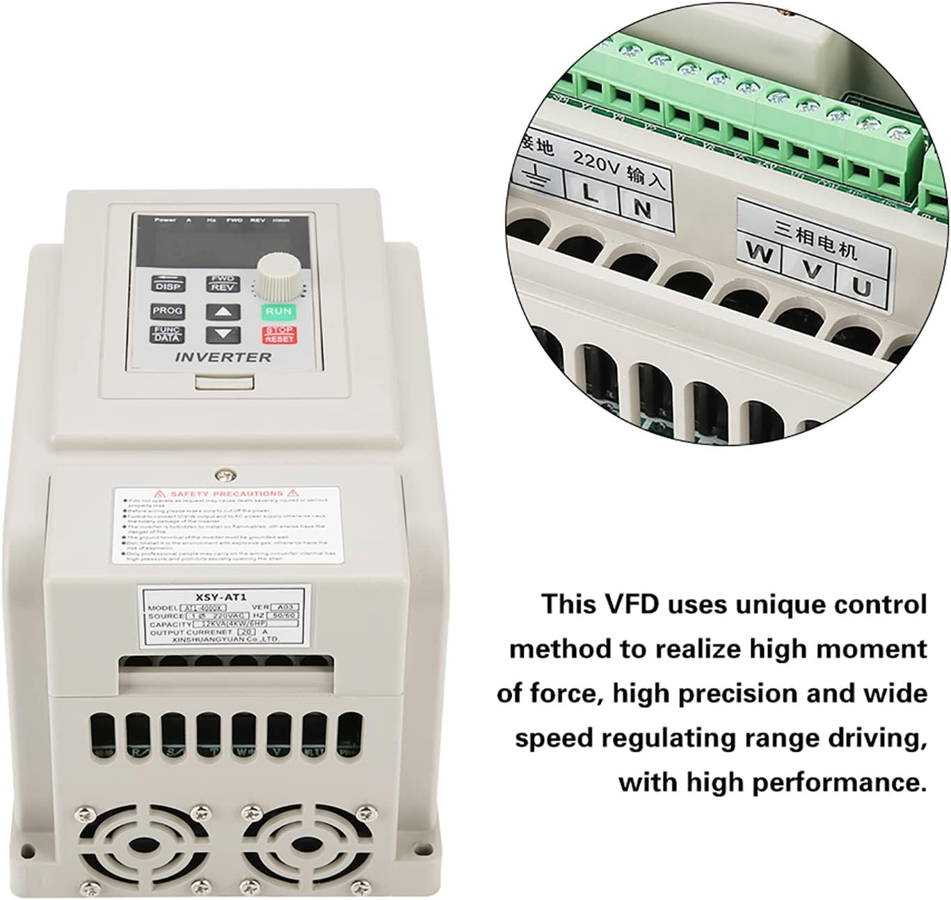
Figure 2: VFD unit with an inset detail of the wiring terminals.
| Terminal | Function | Description |
|---|---|---|
| L, N | AC 220V Single-Phase Input | Connect to the main single-phase AC 220V power supply. |
| U, V, W | Three-Phase AC Motor Output | Connect to the three-phase AC motor. |
| GND | Ground | Connect to a reliable earth ground. |
4. Operating Instructions
4.1 Control Panel Overview
The VFD features an intuitive control panel for easy operation. Familiarize yourself with the buttons and display indicators:

Figure 3: Detailed diagram of the VFD's control panel, labeling buttons, display, and indicator lights.
- 5-digit LED Display: Shows current operating parameters such as frequency, voltage, current, and speed.
- DISP Button: Cycles through different display parameters.
- PROG Button: Enters/exits programming mode.
- FUNC/DATA Button: Used to select functions or confirm data entry in programming mode.
- FWD/REV Button: Toggles motor rotation direction (Forward/Reverse).
- Up/Down Buttons (▲ / ▼): Adjust parameter values or navigate menus.
- RUN Button: Starts the motor.
- STOP/RESET Button: Stops the motor or resets fault conditions.
4.2 Indicator Lights
- FWD: Illuminates when the motor is rotating clockwise.
- REV: Illuminates when the motor is rotating counter-clockwise.
- r/min: Illuminates when the display shows motor speed (revolutions per minute).
- H: Illuminates when the display shows output frequency.
- V: Illuminates when the display shows output voltage.
- A: Illuminates when the display shows output current.
4.3 Basic Operation
- Power On: After ensuring all wiring is correct and secure, apply power to the VFD. The display will light up.
- Set Frequency: Use the Up/Down buttons to adjust the desired output frequency. This directly controls the motor speed.
- Start Motor: Press the RUN button to start the motor. The FWD or REV indicator will light up depending on the direction.
- Change Direction: While the motor is running, press the FWD/REV button to change the rotation direction.
- Stop Motor: Press the STOP/RESET button to stop the motor.
- View Parameters: Press the DISP button to cycle through various operating parameters on the LED display.
5. Maintenance
Regular maintenance ensures the longevity and optimal performance of your VFD.
- Cleaning: Periodically clean the exterior of the VFD with a soft, dry cloth. Do not use liquid cleaners or solvents. Ensure ventilation openings are free from dust and debris.
- Inspection: Regularly inspect wiring connections for tightness and signs of wear or damage. Check for any unusual noises or odors during operation.
- Environment: Maintain the VFD in a clean, dry, and well-ventilated environment within its specified operating temperature range.
- Cooling Fans: Ensure the cooling fans are operating correctly and are not obstructed. The internal heat sink (Figure 4) is critical for thermal management.

Figure 4: Internal view of the VFD's heat sink and cooling fans, crucial for thermal management.
6. Troubleshooting
This section provides solutions to common issues you might encounter with the VFD.
| Problem | Possible Cause | Solution |
|---|---|---|
| VFD does not power on | No power supply; incorrect wiring; internal fault. | Check power input (L, N terminals). Verify wiring. If problem persists, contact support. |
| Motor does not start | Incorrect motor wiring; VFD in fault state; frequency set to 0. | Check U, V, W motor connections. Press STOP/RESET to clear faults. Increase frequency setting. |
| Motor runs in wrong direction | Incorrect FWD/REV setting; motor phase sequence. | Press FWD/REV button. If still incorrect, swap any two of the U, V, W motor output wires. |
| Overcurrent/Overload fault | Motor overloaded; acceleration time too short; short circuit. | Reduce motor load. Increase acceleration time parameter. Check motor and wiring for short circuits. |
| Overvoltage/Undervoltage fault | Input voltage outside specified range; deceleration time too short. | Verify input voltage (220V +/- 15%). Increase deceleration time parameter. |
For issues not listed here or if solutions do not resolve the problem, please contact customer support.
7. Specifications
Detailed technical specifications for the Cuifati AT1-4000X VFD:
| Parameter | Value |
|---|---|
| Model | AT1-4000X |
| Rated Voltage | AC 220V (Single-Phase) |
| Input Voltage Range | 220V AC (+/- 15%) |
| Output Voltage | 220V AC (Three-Phase) |
| Adapted Motor Power | 4 kW |
| Control Method | V/F Open Loop Control |
| Output Voltage Regulation Method | PWM Control |
| Rated Current | 20 A |
| Input Frequency | 50/60 Hz |
| Output Frequency Range | 0 - 400 Hz |
| Input Phase | 1 Phase |
| Output Phase | 3 Phases |
| Package Dimensions | 22 x 21 x 17 cm |
| Weight | 1.58 kg |
| Recommended Uses | Industrial |
| Included Components | 1 x Variable Frequency Drive |
Note: Due to product updates, new and old versions of this product may be shipped randomly. Both versions maintain the same core functionality and specifications.
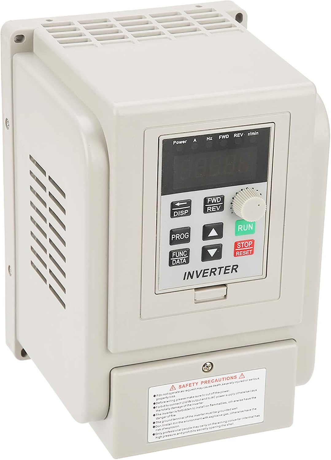
Figure 5: Comparison of new and old models of the Cuifati AT1-4000X VFD.
8. Warranty and Support
For any issues with the product, please contact the manufacturer or your point of purchase for assistance. Information regarding specific warranty periods and support contact details may be provided with your purchase documentation.
The manufacturer can be contacted at any time for product-related concerns, as indicated in the product features.


