1. Introduction
The Walfront PLJ 8LED H RF Frequency Counter Cymometer Tester Module is a high-precision instrument designed for measuring radio frequency signals across a wide range. Utilizing a Microchip PIC16F648A microcontroller and a temperature-compensated voltage-controlled crystal oscillator (VC-TCXO), this module provides accurate frequency readings with a clear 8-digit LED display.
Key Features:
- Single-ended input design with three measurement channels: Low Channel, High Channel, and Auto Channel.
- Equipped with a 2.5 ppm VC-TCXO for enhanced frequency stability and accuracy.
- Features a unique gate control and time algorithm for precise measurements.
- Adjustable gate (display refresh) times: 0.01 seconds, 0.1 seconds, and 1.0 seconds for real-time frequency display.
- Wide measurement range from 0.1 MHz up to 2.4 GHz.
2. Safety Information
Please read and understand all safety instructions before operating the device. Failure to follow these instructions may result in electric shock, fire, or damage to the module.
- Power Supply: Ensure the power supply voltage and current ratings match the module's requirements. Using an incorrect power supply can damage the device.
- Handling: Handle the module with care to avoid damaging sensitive electronic components. Avoid static discharge by grounding yourself before handling.
- Environment: Operate the module in a dry, clean environment, away from moisture, dust, and extreme temperatures.
- Connections: Always ensure proper polarity when connecting power and signal inputs. Incorrect connections can lead to malfunction or damage.
- Maintenance: Do not attempt to modify or repair the module yourself. Refer to qualified personnel for any servicing needs.
3. Package Contents
Verify that all items listed below are included in your package:
- 1 x PLJ 8LED H RF Frequency Counter Cymometer Tester Module
- 2 x Connecting Wires (Red/Black)

Image: The PLJ 8LED H RF Frequency Counter module shown with its two included connecting wires.
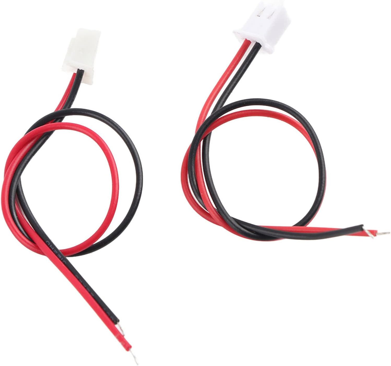
Image: A close-up view of the red and black connecting wires supplied with the module.
4. Product Overview
The PLJ 8LED H module features an 8-digit LED display for clear frequency readings and two control buttons for operation. The circuit board is designed for compact integration into various projects.

Image: Front view of the frequency counter module, highlighting the blue backlit 8-digit LED display showing a frequency measurement.

Image: An angled perspective of the module, illustrating the unlit LED segments and the two small control buttons located on the right side.

Image: The underside of the frequency counter module, revealing the printed circuit board (PCB) with various electronic components.
5. Specifications
| Parameter | Value |
|---|---|
| Model | PLJ-8LED-H |
| Display Type | 8-digit LED (Backlit Font Blue) |
| Gate Time Options | 0.01 S, 0.10 S, 1.0 S |
| Low Channel Measurement Range | 0.1 MHz ~ 60 MHz |
| Low Channel Accuracy (0.01 S gate) | ± 100Hz |
| Low Channel Accuracy (0.1 S gate) | ± 10Hz |
| Low Channel Accuracy (1.0 S gate) | ± 1Hz |
| Low Channel Sensitivity (0.1-10 MHz) | Better than 60mVPP |
| Low Channel Sensitivity (10-60 MHz) | Better than 60mVPP |
| High Channel Measurement Range | 20 MHz ~ 2.4 GHz (divided by 64) |
| High Channel Accuracy (0.01 S gate) | ± 6400Hz |
| High Channel Accuracy (0.1 S gate) | ± 640Hz |
| High Channel Accuracy (1.0 S gate) | ± 64Hz |
| High Channel Sensitivity (20-30 MHz) | Better than 100mVPP |
| High Channel Sensitivity (30-60 MHz) | Better than 50mVPP |
| Auto Channel Identification Frequency | 60 MHz |
| Oscillator Type | VC-TCXO (2.5 ppm) |
| Dimensions (L x W x H) | 5.91 x 1.18 x 0.98 inches (approx.) |
| Weight | 52 Grams (approx.) |
6. Setup
Follow these steps to set up your frequency counter module:
- Power Connection: Connect an appropriate DC power supply (typically 7V-12V, though not explicitly stated in the provided A+ content, common for such modules) to the power input terminals using the provided red and black wires. Ensure correct polarity: red for positive (+), black for negative (-).
- Signal Input: Connect the signal source you wish to measure to the module's input terminal. The module features a single-ended input design.
7. Operating Instructions
Once powered on, the module will display the measured frequency on its 8-digit LED screen. The two small buttons on the module are used for controlling its functions.

Image: The frequency counter module actively displaying a frequency of 29.600.000 Hz on its blue LED screen.
- Channel Selection: The module supports Low Channel, High Channel, and Auto Channel modes. The Auto Channel automatically selects between low and high channels based on the input signal frequency, identifying frequencies around 60 MHz. If the input signal amplitude is insufficient for automatic selection above 60 MHz, manual channel selection may be required. Use the control buttons to cycle through these modes.
- Gate Time Adjustment: The gate time determines how long the module samples the signal before updating the display. Shorter gate times (e.g., 0.01 S) provide faster updates but lower accuracy, while longer gate times (e.g., 1.0 S) offer higher accuracy but slower updates. Use the control buttons to select the desired gate time (0.01 S, 0.10 S, or 1.0 S).
- Reading the Display: The 8-digit LED display shows the measured frequency in Hertz (Hz). Depending on the frequency range, the display will automatically adjust to show the most significant digits.
8. Maintenance
Proper maintenance ensures the longevity and optimal performance of your frequency counter module.
- Cleaning: Gently wipe the module with a soft, dry cloth to remove dust and debris. Do not use liquid cleaners or solvents, as they may damage the electronic components.
- Storage: Store the module in a cool, dry place, away from direct sunlight, high humidity, and extreme temperatures. Keep it in its original packaging or a protective case when not in use to prevent physical damage.
- Inspection: Periodically inspect the connecting wires and terminals for any signs of wear, corrosion, or damage. Replace any damaged components immediately.
9. Troubleshooting
If you encounter issues with your frequency counter module, refer to the following common problems and solutions:
| Problem | Possible Cause | Solution |
|---|---|---|
| No display when powered on | Incorrect power supply voltage or polarity; Loose power connection; Damaged module. | Verify power supply voltage and polarity. Ensure power wires are securely connected. If issues persist, the module may be damaged. |
| Inaccurate frequency readings | Incorrect channel selected; Signal amplitude too low or too high; Interference from other devices; Module calibration issue. | Ensure the correct channel (Low, High, Auto) is selected for the input frequency. Check signal amplitude. Minimize external interference. |
| No frequency detected (display shows '0' or erratic values) | No signal input; Signal input connection loose or incorrect; Signal frequency outside module's range; Signal amplitude too low. | Verify signal source is active and connected properly. Ensure signal frequency is within the module's specified range (0.1 MHz - 2.4 GHz). Increase signal amplitude if possible. |
| Buttons not responding | Physical damage to buttons; Internal circuit issue. | Inspect buttons for physical damage. If no visible damage, contact support. |
10. Warranty and Support
For warranty information or technical support, please refer to the product's purchase documentation or contact the seller directly through the platform where the product was purchased. Keep your purchase receipt as proof of purchase.
For general inquiries about Walfront products, you may visit the official Walfront store on Amazon: Walfront Amazon Store.


