
1. Introduction
This manual provides detailed instructions for the installation, operation, and maintenance of the JESSINIE Modbus-RTU 4-Channel Relay Module. This module is designed for industrial control applications, offering 4-way input signal detection and 4-way relay output via standard Modbus RTU protocol over RS485 or TTL UART interfaces.
Please read this manual thoroughly before using the product to ensure proper operation and to prevent damage.
2. Safety Information
- Ensure the power supply voltage (DC 7-24V) matches the module's requirements. Incorrect voltage can damage the device.
- Disconnect power before making any wiring connections or disconnections.
- Avoid touching live components when the module is powered.
- This module is intended for use by qualified personnel familiar with electronic circuits and Modbus communication.
- Do not expose the module to moisture, extreme temperatures, or corrosive environments.
- The optocoupler input signal range is DC 3.3-30V. Do not exceed this range.
3. Package Contents
Please check the package for the following items:
- 1 x JESSINIE Modbus-RTU 4-Channel Relay Module
- (Note: Additional cables or power supplies are typically sold separately.)
4. Product Features
- On-board mature and stable 8-bit MCU and MAX485 level conversion chips.
- Supports standard Modbus RTU protocol.
- Communication interfaces: RS485 / TTL UART.
- Selectable baud rates: 4800/9600/19200 bps (default 9600bps).
- Supports power-failure storage for settings.
- Optocoupler input signal range: DC 3.3-30V.
- Power supply voltage: DC 7-24V (DC seat/5.08mm terminal), with anti-reverse connection protection.
- 4-channel 5V, 10A/250V AC, 10A/30V DC relays with diode laxative protection.
- Relay output modes: Manual, Flash-off, Flash-on.
- Flash-off/Flash-on delay base: 0.1S, max time: 6553.5S.
- Onboard relay switch indicators.
5. Component Identification
Refer to the images below for a visual guide to the module's components and dimensions.

Figure 5.1: Top View of the Module. This image shows the overall layout of the relay module from above, highlighting the four blue relays, green terminal blocks for inputs and outputs, the DC power jack, and various integrated circuits.

Figure 5.2: Module Dimensions. This view provides the physical dimensions of the module, showing a length of 93mm and a width of 87mm, useful for enclosure design and mounting.
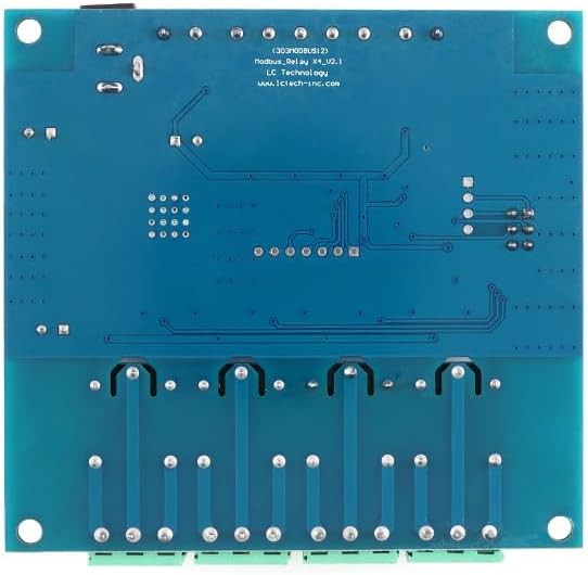
Figure 5.3: Bottom View of the Module. This image displays the underside of the PCB, showing solder points and traces, indicating the manufacturing quality and layout of the board's reverse side.
Key Components:
- DC Power Jack (DC7-24V): For connecting the main power supply.
- 5.08mm Power Terminal (DC7-24V): Alternative power input.
- RS485/TTL Communication Terminals: For data communication (RXD, TXD, DI, RO, GND, 5V).
- Input Signal Terminals (IN1-IN4): For connecting external DC 3.3-30V input signals.
- Relay Output Terminals (NOx, COMx, NCx): Normally Open, Common, Normally Closed contacts for each of the 4 relays.
- Relay Status LEDs: Indicators for each relay's activation status.
6. Setup and Installation
6.1 Power Supply Connection
Connect a DC power supply (7-24V) to either the DC power jack or the 5.08mm terminal block labeled "DC7-24V". Ensure correct polarity if using the terminal block (+ to +, - to -). The module has anti-reverse connection protection.
6.2 Communication Interface Connection
The module supports both RS485 and TTL UART communication.
- RS485: Connect your RS485 master device to the A and B terminals on the module. Ensure proper A/B (Data+/Data-) connection.
- TTL UART: Connect your TTL device (e.g., microcontroller) to the RXD, TXD, and GND pins.
6.3 Input Signal Connection
Connect external DC 3.3-30V signals to the IN1, IN2, IN3, IN4 terminals. These inputs are opto-isolated. Connect the signal ground to the GND terminal next to the inputs.
6.4 Relay Output Connection
Each relay has three terminals: Normally Open (NO), Common (COM), and Normally Closed (NC). Connect your load according to the desired switching behavior:
- Normally Open (NO) & Common (COM): The circuit is open when the relay is off and closes when the relay is activated.
- Normally Closed (NC) & Common (COM): The circuit is closed when the relay is off and opens when the relay is activated.
Ensure the load's voltage and current ratings do not exceed the relay's maximum (10A/250V AC, 10A/30V DC).
7. Operating Instructions
7.1 Modbus RTU Protocol Basics
The module communicates using the standard Modbus RTU protocol. Each command consists of a device address, function code, data address, data, and a CRC checksum.
- Device Address: Configurable from 1 to 255 (default 255).
- Baud Rate: 4800, 9600 (default), 19200 bps.
- Data Format: 8 data bits, 1 stop bit, no parity (8N1).
7.2 Common Modbus Function Codes and Registers
The module uses specific Modbus function codes and register addresses to control relays and read status. Below are common operations:
| Function | Modbus Function Code | Register Address (Hex) | Description |
|---|---|---|---|
| Read Coil Status (Relay Output) | 0x01 (Read Coils) | 0x0000 - 0x0003 | Read the ON/OFF status of relays 1-4. |
| Force Single Coil (Control Relay) | 0x05 (Write Single Coil) | 0x0000 - 0x0003 | Set a single relay ON (0xFF00) or OFF (0x0000). |
| Force Multiple Coils (Control Relays) | 0x0F (Write Multiple Coils) | 0x0000 - 0x0003 | Set multiple relays ON/OFF simultaneously. |
| Read Discrete Inputs (Input Signals) | 0x02 (Read Discrete Inputs) | 0x0000 - 0x0003 | Read the status of input signals IN1-IN4. |
| Read Holding Registers (Module Parameters) | 0x03 (Read Holding Registers) | (Specific addresses vary, refer to detailed protocol document if available) | Read device address, baud rate, relay modes, flash times. |
| Preset Multiple Registers (Set Module Parameters) | 0x10 (Write Multiple Registers) | (Specific addresses vary, refer to detailed protocol document if available) | Set device address, baud rate, relay modes, flash times. |
Note: Specific register maps for setting device address, baud rate, and flash modes are typically provided in a detailed protocol specification from the manufacturer. This table provides general Modbus function codes.
7.3 Relay Operating Modes
The relays can operate in manual, flash-off, or flash-on modes. These modes are typically configured via Modbus commands by writing to specific holding registers.
- Manual Mode: Relay state is directly controlled by Modbus commands (ON/OFF).
- Flash-Off Mode: When activated, the relay turns ON for a set duration and then automatically turns OFF.
- Flash-On Mode: When activated, the relay turns OFF for a set duration and then automatically turns ON.
The delay time for flash modes is set in units of 0.1 seconds, with a maximum duration of 6553.5 seconds (0xFFFF * 0.1S).
8. Specifications
| Brand | JESSINIE |
| Model | Modbus-RTU 4-Channel Relay Module |
| Power Supply | DC 7-24V |
| Communication Interface | RS485 / TTL UART |
| Communication Protocol | Standard Modbus RTU |
| Baud Rate | 4800 / 9600 (default) / 19200 bps |
| Device Address | 1-255 (default 255) |
| Input Signal Range | DC 3.3-30V (Optocoupler isolated) |
| Relay Channels | 4 |
| Relay Contact Rating | 10A/250V AC, 10A/30V DC |
| Relay Life | 100,000 operations (approx.) |
| Flash Mode Delay Base | 0.1S |
| Max Flash Delay Time | 6553.5S |
| Dimensions | 93mm x 87mm (approx.) |
9. Troubleshooting
- Module Not Powering On:
- Check power supply voltage (must be DC 7-24V).
- Verify power supply connections and polarity.
- Ensure the power supply is functional.
- No Communication:
- Verify RS485 A/B connections or TTL RX/TX/GND connections.
- Check baud rate, device address, and data format (8N1) settings on both the module and the master device.
- Ensure the Modbus master is sending correct commands and CRC checksums.
- Confirm the communication interface (RS485 or TTL) is correctly selected/wired.
- Relays Not Activating:
- Check if the module is powered and communicating correctly.
- Verify the Modbus command to activate the relay is correct (function code, register address, value).
- Ensure the load connected to the relay is within its voltage and current ratings.
- Check the relay status LEDs; if they light up but the load doesn't activate, check load wiring.
- Input Signals Not Detected:
- Ensure the input signal voltage is within DC 3.3-30V.
- Verify input signal wiring and ground connection.
- Check if the Modbus command to read discrete inputs is correct.
10. Maintenance
- Keep the module clean and free from dust and debris. Use a soft, dry cloth for cleaning.
- Ensure proper ventilation if installed in an enclosure to prevent overheating.
- Regularly inspect wiring connections for tightness and signs of corrosion.
- Avoid exposing the module to strong electromagnetic fields, which can interfere with its operation.
11. Warranty and Support
For warranty information and technical support, please refer to the product's purchase platform or contact JESSINIE customer service directly. Keep your purchase receipt for warranty claims.
For further assistance, you may visit the JESSINIE Store on Amazon.