
1. Introduction
This manual provides detailed instructions for the JESSINIE 1 Channel Modbus RTU Relay Module. This module is designed for industrial control applications, enabling 1-way input signal detection and 1-way relay output via standard MODBUS RTU protocol over RS485 or TTL communication interfaces. It features a stable 8-bit MCU and MAX485 level conversion chips, making it suitable for digital quantity detection or power control scenarios.

Figure 1: Top-down view of the JESSINIE 1 Channel Modbus RTU Relay Module.
2. Product Features
- On-board mature and stable 8-bit MCU and MAX485 level conversion chips for reliable performance.
- Output signal: Relay switch signal supporting manual, flash-off, and flash-on modes. Delay base of flash-off/flash-on is 0.1S, with a maximum time of 6553.5S.
- Equipped with 1 Channel 5V, 10A/250V AC, 10A/30V DC relay, rated for 100,000 continuous closures, featuring diode laxative protection and short response time.
- Communication protocol: Supports standard Modbus RTU protocol.
- Communication interface: Supports RS485/TTL UART interface.
- Communication baud rate: Selectable from 4800/9600/19200 bps, default 9600 bps. Supports power failure storage.
- Optocoupler input signal range: DC3.3-30V (note: this input cannot be used for relay control).
- Power supply voltage: DC7-24V, supports DC seat/5.08mm terminal power supply, with input anti-reverse connection protection.
3. Specifications
| Specification | Value |
|---|---|
| Brand | JESSINIE |
| Model Number | 73788 |
| Connector Type | Screw Terminal |
| Contact Type | Normally Open |
| Current Rating | 10 A |
| Mounting Type | DIN Rail Mount (implied by design, check specific accessories) |
| Operation Mode | Manual (and programmable via Modbus) |
| Coil Voltage | 5V DC (for relay coil) |
| Contact Current Rating | 10 A |
| Maximum Switching Current | 10 A |
| Minimum Switching Voltage | 7V DC (module power supply) |
| Number of Terminals | Multiple (for power, RS485/TTL, input, relay output) |
| Power Supply Voltage | DC7-24V |
| Optocoupler Input Range | DC3.3-30V |
4. Setup Instructions
Careful attention to wiring is crucial for proper operation and to prevent damage to the module or connected devices.
4.1 Power Supply Connection
Connect a DC power source within the range of 7V to 24V to the module's power input terminals. The module supports both a DC seat and 5.08mm terminal power supply. Ensure correct polarity; the module includes anti-reverse connection protection.

Figure 2: Angled view of the module, highlighting power input terminals on the left.
4.2 Communication Interface Connection (RS485/TTL)
The module supports both RS485 and TTL UART communication. Identify the appropriate terminals for your chosen interface:
- RS485: Connect your RS485 bus to the A+ and B- terminals.
- TTL UART: Connect your TTL device to the RXD, TXD, and GND terminals.
Ensure the communication baud rate on your host device matches the module's setting (default 9600 bps).
4.3 Optocoupler Input Connection
The module has a 1-way optocoupler input. Connect your input signal (DC3.3-30V) to the designated input terminals. Note that this input is for signal detection only and cannot directly control the relay.
4.4 Relay Output Connection
Connect the device you wish to control to the relay output terminals. The relay provides a switch signal and can handle up to 10A at 250V AC or 10A at 30V DC. The terminals are typically labeled NO (Normally Open), COM (Common), and NC (Normally Closed). Refer to the module's silkscreen for exact labeling.
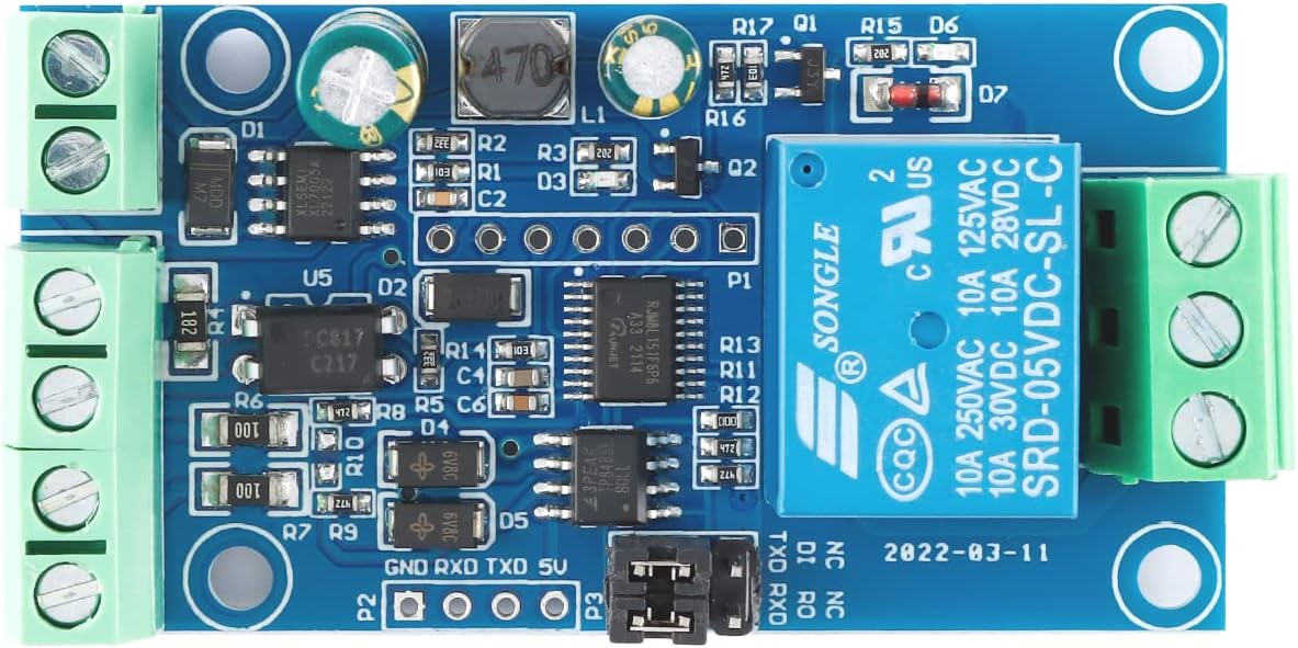
Figure 3: Top view of the module, showing various connection points and components.
5. Operating Instructions
The module operates using the standard Modbus RTU protocol. Communication is established by sending specific commands to the module's address.
5.1 Modbus RTU Protocol
The module's device address can be set within the range of 1-255, with a default of 255. The baud rate can be configured to 4800, 9600 (default), or 19200 bps. These settings support power-down saving, meaning they are retained even after power loss.
You can read the device address, input signal status, and relay status using Modbus RTU commands. Consult the Modbus RTU specification for detailed command structures (e.g., Function Code 03 for reading holding registers, Function Code 06 for writing single holding registers).
5.2 Relay Control Modes
The relay can be controlled in three modes:
- Manual Mode: Direct control of the relay state (ON/OFF) via Modbus commands.
- Flash-Off Mode: The relay turns ON for a specified duration and then turns OFF automatically.
- Flash-On Mode: The relay turns OFF for a specified duration and then turns ON automatically.
The delay duration for flash modes is based on 0.1S increments, allowing for precise timing up to 6553.5 seconds (0xFFFF * 0.1S).
5.3 Indicator Lights
The onboard relay switch indicator provides visual feedback on the relay's current state (ON/OFF).
6. Maintenance
The JESSINIE 1 Channel Modbus RTU Relay Module is designed for durability and requires minimal maintenance. Follow these guidelines to ensure longevity:
- Cleanliness: Keep the module free from dust, dirt, and moisture. Use a soft, dry cloth for cleaning. Avoid using solvents or abrasive cleaners.
- Environmental Conditions: Operate the module within its specified temperature and humidity ranges. Avoid extreme conditions.
- Connections: Periodically check all screw terminal connections to ensure they are secure. Loose connections can lead to intermittent operation or damage.
- Handling: Handle the module with care to avoid physical damage to components or solder joints.
7. Troubleshooting
If you encounter issues with your JESSINIE 1 Channel Modbus RTU Relay Module, consider the following troubleshooting steps:
7.1 No Power / Module Not Responding
- Check Power Supply: Verify that the DC power supply is connected correctly (7-24V) and providing the correct voltage. Ensure polarity is correct, although the module has anti-reverse protection.
- Power Indicator: Check if any power indicator LEDs on the module are illuminated.
- Connections: Ensure power supply wires are securely connected to the terminals.
7.2 Communication Errors (RS485/TTL)
- Wiring: Double-check RS485 A+/B- or TTL RXD/TXD/GND connections for correctness and secure contact.
- Baud Rate: Confirm that the baud rate setting on your host device matches the module's baud rate (default 9600 bps).
- Device Address: Ensure the Modbus device address used in your commands matches the module's configured address (default 255).
- Protocol: Verify that your host is sending commands using the standard Modbus RTU protocol.
- Termination Resistors (RS485): For RS485 networks, ensure proper termination resistors are used if the module is at an end of the bus.
7.3 Relay Not Switching
- Power: Ensure the module is powered on and communicating correctly (see above).
- Modbus Command: Verify that the correct Modbus command is being sent to activate the relay.
- Load: Check the connected load to ensure it is within the relay's specifications (10A/250V AC, 10A/30V DC) and wired correctly to the NO/COM/NC terminals.
- Indicator LED: Observe the relay indicator LED. If it changes state but the load doesn't respond, the issue might be with the load or its wiring.
7.4 Optocoupler Input Not Detecting Signal
- Input Voltage: Verify that the input signal voltage is within the specified range (DC3.3-30V).
- Wiring: Check the wiring of the input signal to the optocoupler input terminals.
- Modbus Read: Ensure you are using the correct Modbus command to read the status of the optocoupler input.
8. Warranty and Support
For warranty information or technical support regarding your JESSINIE 1 Channel Modbus RTU Relay Module, please refer to the product's purchase documentation or contact JESSINIE customer service through the vendor's website or your point of purchase. Please have your model number (73788) and purchase details available when contacting support.