
1. Introduction
This user manual provides comprehensive instructions for the installation, configuration, and operation of the Diatone Mamba Basic F405 MK2 Flight Controller. Designed for advanced drone applications, this flight controller integrates essential components for stable and responsive flight performance. Please read this manual thoroughly before proceeding with installation and setup.
2. Product Overview

Figure 2.1: Top view of the Diatone Mamba Basic F405 MK2 Flight Controller, showcasing its compact design and component layout.
The Mamba Basic F405 MK2 is a high-performance flight controller featuring an STM32F405 MCU and MPU6000 Gyro, optimized for 3-6S LiPo input. It includes dual BECs (5V/2A and 9V/2A) and an AT7456E OSD for on-screen display. Its compact 30.5x30.5mm mounting hole pattern makes it suitable for various drone frames.
3. Specifications
3.1. Flight Controller Specifications
- Firmware Target: FURYF4OSD
- Input Voltage: 3-6S LiPo (12.6-25V)
- BEC: 5V/2A & 9V/2A
- MCU: STM32F405
- Gyro: MPU6000
- Flash: 16MB
- OSD: AT7456E
- Mounting Hole: 30.5x30.5mm, M3
- Weight: 6g
- Dimensions: 4 x 4 x 1 inches (Product Dimensions)
- Item Weight: 0.634 ounces
- Material: Plastic
- Total USB Ports: 1

Figure 3.1: Detailed pinout diagram and stack specifications for the Mamba F405 MK2 Flight Controller.
4. Package Contents
Upon opening the package, verify that all items listed below are present and in good condition:
- 1x Mamba F405 Mk2 Flight Controller
- 1x Mounting Hardware Set
- 1x User Manual (this document)
5. Setup and Wiring
Proper wiring is critical for the safe and correct operation of your flight controller. Refer to the diagrams below for connection points.
5.1. Pinout Overview
The Mamba F405 MK2 features clearly labeled pads for various connections. Key pads include:
- 5V / 9V / 3.3V: Regulated power outputs for peripherals.
- GND: Ground connections.
- TX / RX: UART (Universal Asynchronous Receiver/Transmitter) pads for serial communication (e.g., GPS, VTX, Receiver).
- SBUS / PPM: Receiver input pads.
- LED: LED strip output.
- BOOT: Bootloader button for firmware flashing.
- CURR: Current sensor input.
- RSSI: Received Signal Strength Indicator input.
- Buzzer: Buzzer output pads.
The default UART assignments are:
- UART 1: Receiver
- UART 3: VTX
- UART 6: Telemetry
The power indicator LEDs provide visual feedback on the flight controller's status:
- LED (on/off): Indicates 3.3V power status.
- Gyro (Blue): Gyro status.
- MCU (Green): MCU status.
- 5V (White): 5V power status.
- VCC (Red): Main power input status.
5.2. Wiring Diagrams
Refer to the following diagrams for connecting various components to the flight controller. Ensure all connections are secure and correctly polarized to prevent damage.
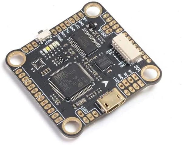
Figure 5.1: Top view of the flight controller, showing the layout of major components and connection pads.

Figure 5.2: Bottom view of the flight controller, highlighting power regulation components.

Figure 5.3: Close-up view of the Micro USB port for connecting to a computer.
Figure 5.4: Comprehensive wiring diagram illustrating connections for receiver (MSR, Crossfire, SBUS), camera, VTX, buzzer, GPS module, and LED strips. This diagram is crucial for integrating the flight controller into a complete drone system.
For detailed wiring instructions for specific components (e.g., ESCs, motors), refer to the respective component manuals and the Betaflight documentation.
6. Operating Instructions
6.1. Firmware Flashing
The Mamba Basic F405 MK2 uses the FURYF4OSD firmware target. To flash or update the firmware:
- Download the latest Betaflight Configurator from the official Betaflight GitHub page.
- Connect the flight controller to your computer using a Micro USB cable.
- If the flight controller does not automatically enter DFU mode, press and hold the BOOT button while connecting the USB cable.
- In Betaflight Configurator, navigate to the "Firmware Flasher" tab.
- Select "FURYF4OSD" as the board target.
- Choose the desired firmware version and click "Load Firmware [Online]".
- Click "Flash Firmware" to begin the flashing process. Do not disconnect the flight controller until the process is complete.
6.2. Initial Configuration (Betaflight)
After flashing, disconnect and reconnect the flight controller. Open Betaflight Configurator and connect to the flight controller. Proceed with the following basic configuration steps:
- Ports Tab: Configure UARTs for your receiver, VTX, GPS, etc., based on your wiring.
- Configuration Tab: Set up ESC protocol (e.g., DShot), accelerometer calibration, board alignment, and other essential parameters.
- Receiver Tab: Verify receiver input and channel mapping.
- Modes Tab: Assign arming, flight modes, and other switches to your radio channels.
- Motors Tab: Test motor direction (remove propellers before testing!).
For detailed configuration, refer to the extensive Betaflight documentation and community resources.
7. Maintenance
To ensure the longevity and optimal performance of your Mamba Basic F405 MK2 Flight Controller, follow these maintenance guidelines:
- Keep Clean: Regularly inspect the board for dust, debris, or solder splashes. Use a soft brush or compressed air to clean.
- Avoid Moisture: Protect the flight controller from water and high humidity. If exposed, ensure it is completely dry before powering on.
- Static Discharge: Handle the flight controller by its edges and avoid touching components directly, especially in dry environments, to prevent electrostatic discharge (ESD) damage.
- Secure Mounting: Ensure the flight controller is securely mounted to the frame to minimize vibrations, which can affect gyro performance.
- Inspect Connections: Periodically check all solder joints and connectors for looseness or corrosion.
8. Troubleshooting
If you encounter issues with your flight controller, consider the following common troubleshooting steps:
- No Power/LEDs Off:
- Check input voltage and polarity from the battery.
- Inspect power pads for short circuits or poor solder joints.
- Cannot Connect to Betaflight Configurator:
- Ensure correct USB drivers are installed (e.g., STM32 Virtual COM Port Driver, Zadig for DFU mode).
- Try a different USB cable or port.
- Attempt to connect in DFU mode (hold BOOT button while plugging in USB).
- Motors Not Spinning/Incorrectly:
- Verify ESC connections and protocol settings in Betaflight.
- Check motor direction and remap if necessary.
- Ensure motors are armed (check arming conditions in Betaflight).
- No OSD Display:
- Check OSD settings in Betaflight (Video Format, elements enabled).
- Verify camera and VTX connections to the OSD pads.
- Unstable Flight:
- Recalibrate accelerometer.
- Check for excessive vibrations (soft-mounting FC if needed).
- Review PID tuning settings.
For more advanced troubleshooting, consult online forums and the Betaflight documentation.
9. Warranty and Support
DIATONE products are manufactured with high standards of quality and performance. For specific warranty information, please refer to the official DIATONE website or contact your point of purchase.
For technical support, FAQs, and additional resources, please visit the official DIATONE support pages:
Manufacturer: Diatone