1. Introduction
This manual provides essential information for the safe and efficient operation of your Eventek DPS-305 Programmable DC Power Supply. Please read this manual thoroughly before using the device to ensure proper functionality and to prevent damage or injury. This power supply is designed for laboratory, educational, and general electronic testing applications, offering precise control over voltage and current output.
2. Safety Instructions
- Always connect the power supply to a grounded AC outlet.
- Do not operate the device in wet or damp conditions.
- Ensure proper ventilation around the unit to prevent overheating. Do not block ventilation openings.
- Before connecting or disconnecting test leads, ensure the output is turned off.
- Do not exceed the maximum rated voltage and current of the device or the connected load.
- In case of smoke, unusual odors, or abnormal operation, immediately disconnect the power supply from the AC outlet and contact support.
- Only qualified personnel should attempt repairs.
3. Package Contents
Verify that all items are present in the package:
- Eventek DPS-305 DC Power Supply Unit
- AC Power Cable
- Banana Plug Test Leads (Red and Black)
- User Manual (this document)
4. Product Overview
Familiarize yourself with the components of your Eventek DPS-305 power supply.
4.1 Front Panel

The front panel features a large 4-digit LED display for voltage, current, and power readings. It includes control knobs for voltage and current adjustment, memory buttons (M1, M2, M3), an Over Current Protection (OCP) button, an Output On/Off button, a 5V/3.6A USB output port, and main output terminals (positive, negative, and ground).
4.2 Encoder Adjustment Knobs
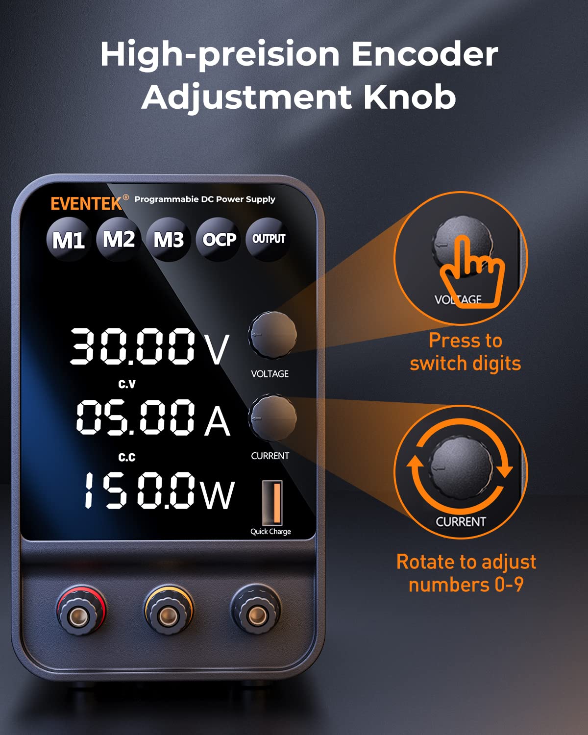
The voltage and current adjustment knobs are precision encoder types. Pressing a knob allows you to select a specific digit on the display, which can then be adjusted by rotating the knob. This enables fine-tuning of output parameters.
4.3 High Precision Display

The backlit 4-digit LED display provides accurate readings for voltage (up to 0.01V) and current (up to 0.001A). It also automatically calculates and displays the output power in watts.
4.4 Memory Storage Function
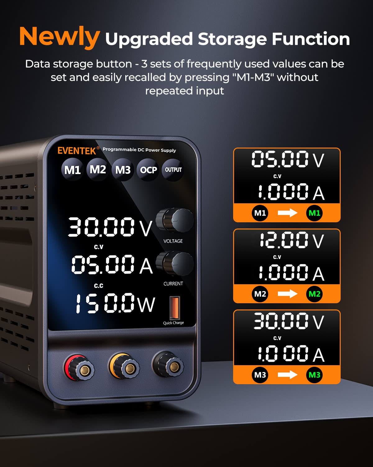
The M1, M2, and M3 buttons allow you to save and quickly recall three sets of frequently used voltage and current settings, streamlining repetitive tasks.
4.5 USB Quick Charge Interface

A dedicated 5V/3.6A USB output port is available on the front panel for convenient charging of mobile phones or other USB-powered devices.
4.6 Safety Features

The power supply incorporates multiple safety features, including overheat protection, voltage overload protection, and short circuit protection. In the event of a short circuit, a buzzer alarm will sound, and the output will automatically stop to protect the unit and the connected load.
5. Setup
- Placement: Place the power supply on a stable, level surface with adequate ventilation. Ensure no objects obstruct the air vents on the sides and rear of the unit.
- Power Connection: Connect the supplied AC power cable to the power input socket on the rear of the unit, then plug the other end into a grounded AC power outlet.
- Initial Power On: Flip the power switch located on the rear of the unit to the "ON" position. The display will illuminate.
- Output Leads: Connect the banana plug test leads to the output terminals on the front panel. The red lead connects to the positive (+) terminal, and the black lead connects to the negative (-) terminal. The green terminal is for ground.
6. Operating Instructions
6.1 Setting Voltage and Current
- Turn Off Output: Ensure the output is off by pressing the OUTPUT button. The output indicator will be off.
- Adjust Voltage:
- Press the VOLTAGE knob to select the digit you wish to adjust (the selected digit will blink).
- Rotate the VOLTAGE knob to change the value of the selected digit.
- Repeat until the desired voltage is set.
- Adjust Current:
- Press the CURRENT knob to select the digit you wish to adjust.
- Rotate the CURRENT knob to change the value of the selected digit.
- Repeat until the desired current limit is set.
- Enable Output: Once voltage and current limits are set, connect your load to the output terminals. Press the OUTPUT button to enable the output. The output indicator will light up.
6.2 Using Memory Functions (M1, M2, M3)
- Saving Settings:
- Set the desired voltage and current using the respective knobs.
- Press and hold one of the memory buttons (M1, M2, or M3) for approximately 3 seconds until a beep sounds or the display indicates saving. The current settings are now stored.
- Recalling Settings:
- Briefly press the desired memory button (M1, M2, or M3). The stored voltage and current values will be loaded onto the display.
- Remember to press the OUTPUT button to enable the output with the recalled settings.
6.3 Over Current Protection (OCP)
The OCP function protects the connected load from excessive current. When OCP is enabled and the output current exceeds the set limit, the power supply will automatically cut off the output and sound an alarm.
- Enable/Disable OCP: Press the OCP button to toggle the Over Current Protection function on or off. An indicator on the display will show its status.
- Adjust OCP Limit: The OCP limit is typically set by the current limit knob. Ensure your current limit is set appropriately for your application.
6.4 Using the USB Output
The 5V/3.6A USB output port can be used to charge compatible USB devices. Simply connect your device's USB cable to this port. This output is independent of the main DC output settings.
7. Maintenance
- Cleaning: Disconnect the power supply from the AC outlet before cleaning. Use a soft, dry cloth to wipe the exterior. Do not use abrasive cleaners or solvents.
- Ventilation: Regularly check that the ventilation openings are clear of dust and debris.
- Storage: When not in use for extended periods, store the power supply in a cool, dry place, away from direct sunlight and extreme temperatures.
8. Troubleshooting
| Problem | Possible Cause | Solution |
|---|---|---|
| No display after power on. | Power cable not connected or power switch off. | Check power cable connection and ensure the rear power switch is ON. |
| No output voltage/current. | Output button is off, or OCP is triggered. | Press the OUTPUT button to enable. Check OCP status and reset if triggered. Ensure test leads are properly connected. |
| Buzzer alarm sounds, output stops. | Short circuit or overcurrent condition detected. | Immediately disconnect the load. Identify and resolve the short circuit or overcurrent issue. Reset the power supply by turning off and on, or by disabling and re-enabling output. |
| Inaccurate readings. | External factors or calibration needed. | Ensure proper connections. If persistent, contact customer support for potential calibration guidance. |
9. Specifications
| Parameter | Value |
|---|---|
| Model | DPS-305 |
| Input Voltage | AC 110V/220V (Switchable, check rear panel) |
| Output Voltage Range | 0-30V DC |
| Output Current Range | 0-5A DC |
| Output Power | 150W |
| Voltage Display Accuracy | ±0.01V |
| Current Display Accuracy | ±0.001A |
| USB Output | 5V/3.6A |
| Cooling Method | Air Cooling (Intelligent Fan Control) |
| Dimensions (L x W x H) | Approximately 10.79 x 8.35 x 4.84 inches |
| Weight | Approximately 3.46 Pounds |
10. Warranty and Support
Eventek is committed to providing high-quality products and customer satisfaction. Your Eventek DPS-305 DC Power Supply comes with a manufacturer's warranty against defects in materials and workmanship under normal use.
For technical assistance, troubleshooting, or warranty claims, please contact Eventek customer support. Our team is available to provide 24-hour support to address any issues you may encounter with the product.
Please refer to the official Eventek website or your purchase documentation for specific warranty terms and contact information.


