
1. Introduction
The PROSTER ET612 is a multi-functional network cable tester designed for comprehensive network maintenance and troubleshooting. It combines capabilities for network cable testing, Power over Ethernet (POE) testing, wire tracking, continuity testing, and voltage measurement. This manual provides detailed instructions for the safe and effective use of your ET612 device.
2. Safety Information
- Always read and understand this manual before operating the device.
- Do not attempt to test live circuits exceeding 60V to prevent damage to the device and personal injury.
- Ensure batteries are correctly installed according to polarity markings.
- Do not expose the device to moisture or extreme temperatures.
- Keep the device away from children.
3. Package Contents
Verify that all items are present in your package:
- PROSTER ET612 Main Tester Unit
- PROSTER ET612 Wire Tracker Receiver
- RJ45 Adapter Cable
- Alligator Clip Test Cable
- Cable Stripper Tool
- Storage Bag
- AAA Batteries (3 included)

Image 3.1: PROSTER ET612 Network Cable Tester with its accessories, including the main unit, receiver, cables, stripper, and storage bag.
4. Product Overview
The PROSTER ET612 consists of a main tester unit and a wire tracker receiver. Familiarize yourself with the components and controls as shown below:

Image 4.1: Detailed diagram showing the labeled parts of the PROSTER ET612 main unit and receiver.
- External Probe Connector
- Power Switch
- Voltage Detecting Button (V)
- Cable Testing Button (TEST)
- Display (LCD Screen)
- Cable Tracing Button (SCAN)
- Continuity Test Button (Ω)
- Signal Selection Button (HZ)
- Pairing Speed Adjusting Button (SLOW/FAST)
- Battery Door (Main Unit)
- RJ45 Connector (Receiver)
- Indicators (Receiver LEDs)
- Mode Button (Receiver)
- Flashlight Switch (Receiver)
- Scan Ready Indicator (Receiver)
- Flashlight (Receiver)
- Volume Adjusting Wheel (Receiver)
- Tracing Probe (Receiver)
- Battery Door (Receiver)
5. Setup
5.1 Battery Installation
The PROSTER ET612 requires 3 AAA batteries for operation (included). To install or replace batteries:
- Locate the battery door on the back of both the main unit (10) and the receiver (19).
- Open the battery door.
- Insert 3 AAA batteries, ensuring correct polarity (+/-) as indicated inside the compartment.
- Close the battery door securely.
5.2 Powering On/Off
To power on the main unit, press and hold the Power Switch (2) for approximately 5 seconds until the LCD screen illuminates. To power off, press and hold the Power Switch (2) again until the screen turns off.
The receiver unit typically powers on when its mode button is pressed or when the flashlight is activated.
6. Operating Instructions
6.1 Network Cable Collation (RJ45)
This function tests the physical connection status of network cables (RJ45), identifying open circuits, short connections, miswires, and reverse connections.
- Connect one end of the network cable to the RJ45 port on the main unit.
- Connect the other end of the network cable to the RJ45 port on the receiver (11).
- Press the TEST button (4) on the main unit.
- The LCD display on the main unit and the LED indicators (12) on the receiver will show the wiring sequence. A correct connection will show matching numbers on both units. Discrepancies indicate faults.
- Use the SLOW or FAST buttons (9) to adjust the scanning speed.

Image 6.1: The main unit and receiver connected for a network cable test, displaying the wire map.
6.2 POE Testing Function
This function allows testing of standard and non-standard Power over Ethernet (POE) devices, including POE voltage, power supply polarity, and power supply mode.
- Connect the network cable from the POE device (e.g., POE switch) to the POE port on the main unit.
- Press the V button (3) to enter the voltage test mode.
- Press the V button (3) again to switch to POE test mode.
- The LCD display (5) will show the POE voltage, power supply line (flashing numbers indicate positive, non-flashing indicate negative), and power supply mode.

Image 6.2: The main unit connected to a POE switch, showing POE voltage and line information on the display.
6.3 Wire Tracking / Line Finder
The wire tracking function helps quickly locate specific cable pairs among numerous cables. It supports both analog and digital signals.
- Connect one end of the target cable to the RJ45 port on the main unit.
- Press the SCAN button (6) on the main unit to activate the tracing signal.
- On the receiver, press the MODE button (13) to select between Blue (Digital) or Red (Analog) signal indication.
- Use the tracing probe (18) of the receiver to scan the cables. The receiver will emit an audible tone, and the indicators (12) will light up when the target cable is detected.
- Adjust the Volume Adjusting Wheel (17) on the receiver for comfortable listening.
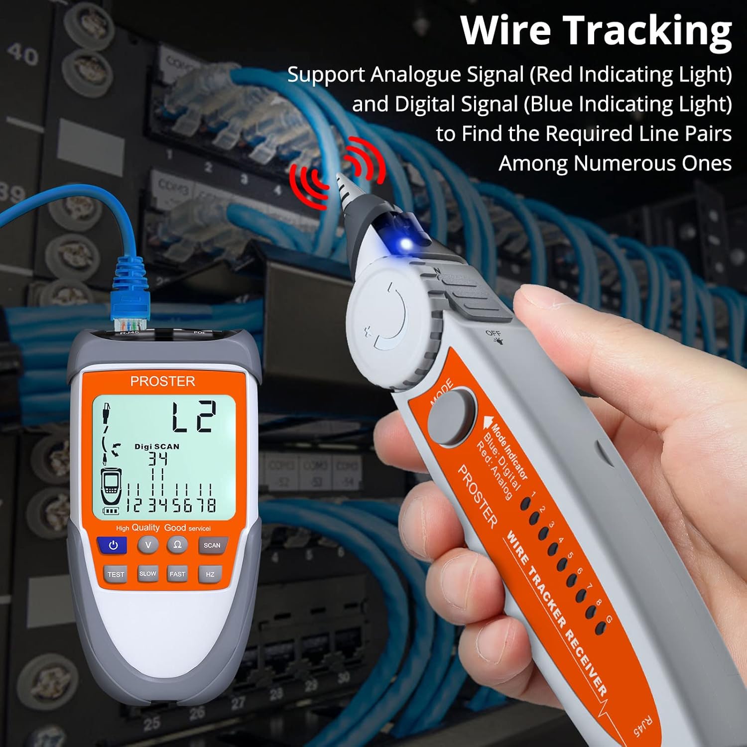
Image 6.3: The wire tracker receiver in use, identifying a specific cable within a bundle.
6.4 Continuity Test (RJ11 and other metal wires)
This function checks for open or short circuits in telephone lines (RJ11) and other metal wires using the alligator clip test cable.
- Connect the alligator clip test cable to the External Probe Connector (1) on the main unit.
- Attach the alligator clips to the two ends of the wire or to the specific pins of the RJ11 connector you wish to test.
- Press the Ω button (7) on the main unit.
- The LCD display (5) will show "00Ω" for a continuous circuit (good connection) or "OL" for an open circuit (no connection).

Image 6.4: The main unit conducting a continuity test, displaying "00Ω" for a closed circuit.
6.5 Voltage Test Function
This function measures battery voltage and checks voltage polarity (up to 60V).
- Connect the alligator clip test cable to the External Probe Connector (1) on the main unit.
- Attach the alligator clips to the positive and negative terminals of the battery or voltage source.
- Press the V button (3) on the main unit.
- The LCD display (5) will show the voltage. Flashing numbers indicate positive polarity, while non-flashing numbers indicate negative polarity.

Image 6.5: The main unit displaying the voltage of a 9V battery during a voltage test.
6.6 LED Flashlight
The receiver unit includes an LED flashlight (16) for use in dark environments.
- To turn on the flashlight, slide the Flashlight Switch (14) on the receiver.
- Slide the switch again to turn it off.

Image 6.6: The receiver's LED flashlight in use, providing illumination in a low-light setting.
7. Maintenance
- Cleaning: Wipe the device with a soft, dry cloth. Do not use abrasive cleaners or solvents.
- Storage: Store the device in its protective bag in a cool, dry place when not in use. Remove batteries if storing for extended periods to prevent leakage.
- Battery Replacement: Replace batteries when the low battery indicator appears on the LCD screen or when the device performance degrades.
8. Troubleshooting
| Problem | Possible Cause | Solution |
|---|---|---|
| Device does not power on. | Low or dead batteries; Power button not held long enough. | Replace batteries. Press and hold the power button for approximately 5 seconds. |
| Inaccurate cable test results. | Poor connection; Damaged cable; Incorrect mode selected. | Ensure cables are securely connected. Inspect cables for damage. Verify the correct test mode is selected. |
| Wire tracker receiver emits constant noise or no signal. | Interference; Main unit not transmitting; Low receiver battery. | Move away from sources of electromagnetic interference. Ensure the main unit is in SCAN mode. Replace receiver batteries. |
| LCD display is dim or unreadable. | Low battery. | Replace batteries in the main unit. |
9. Specifications
| Feature | Detail |
|---|---|
| Model Number | ET612 |
| Brand | PROSTER |
| Power Source | Battery Powered (3 AAA batteries required, included) |
| Min. Operating Voltage | 9 Volts |
| Measurement Type | Voltmeter |
| Product Dimensions (L x W x H) | 22 x 14.8 x 5 cm (Main Unit & Receiver combined) |
| Item Weight | 0.39 Kilograms |
| Color | Orange |
10. Warranty and Support
For warranty information or technical support, please refer to the PROSTER official website or contact your retailer. You can also visit the official PROSTER store on Amazon for more product information: PROSTER Store.

