
1. Introduction
This manual provides detailed instructions for the installation, operation, and maintenance of your diymore 30A 12V/24V PWM Solar Charge Controller. This intelligent controller is designed to manage the power flow from your solar panel to your battery, ensuring efficient charging and protecting your battery from overcharge and over-discharge. It features a large LCD screen, dual USB outputs, and comprehensive 3-stage PWM charge management.
Key Features:
- Light control and time control discharge functionality.
- Compatible with lead-acid batteries (OPEN, AGM, GEL).
- 3-stage PWM charge management: direct charge, boost charge, and float charge.
- Dual MOS reverse current protection, low heat generation.
- Built-in overcurrent, short-circuit, open-circuit, and reverse connection protection.
- Dual USB output (5V/2A Max) for mobile phone charging.
- Automatic 12V/24V voltage identification.
2. Safety Information and Precautions
Please read all safety instructions carefully before installation and operation to prevent damage to the controller, battery, or other components.
- This solar charge controller is designed exclusively for lead-acid batteries (OPEN, AGM, GEL). Do not use it with other battery types, including lithium batteries or nickel-metal hydride batteries.
- The controller can only use photovoltaic panels as its power source. Do not use DC or other power sources as a power source.
- Ensure the battery has sufficient voltage for the controller to recognize its type (12V or 24V) during the first installation.
- Install the controller close to the battery to minimize voltage drop due to excessive wire length, which can affect accurate voltage detection.
- The controller will generate heat during operation. Install it on a flat, well-ventilated surface to ensure proper heat dissipation.
- Always connect the components in the specified order to avoid damage.
3. Product Overview
Familiarize yourself with the components and display of the solar charge controller.

Figure 1: Front view of the diymore 30A 12V/24V PWM Solar Charge Controller, showing the LCD display, control buttons, and USB ports.
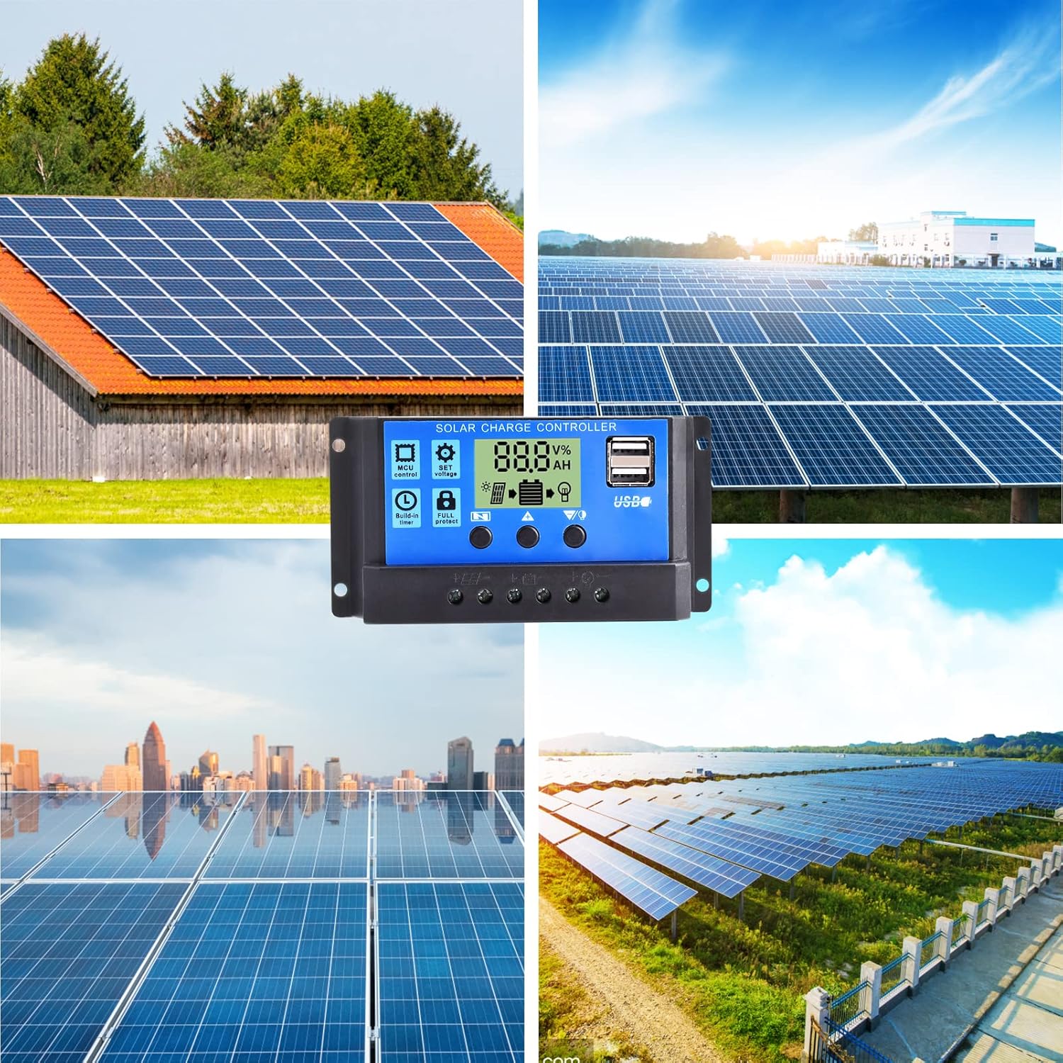
Figure 2: Detailed view of the LCD display and control buttons. The display shows voltage, percentage, and icons for solar panel, battery, and load. Buttons are labeled for Menu, Up, and Down/Manual.
The LCD screen displays various parameters such as voltage, charging/discharging current, accumulated electricity generation, temperature, and battery status. The three buttons below the screen are used for navigation and setting adjustments.
4. Setup and Installation
Follow these steps for proper installation of the solar charge controller. Ensure all connections are secure and correct to prevent damage.
- Prepare the Installation Location: Choose a flat, well-ventilated surface near the battery. Avoid direct sunlight, high temperatures, and humid environments.
- Connect the Battery: Connect the positive and negative terminals of the battery to the corresponding battery terminals on the controller. The controller will automatically detect the battery voltage (12V or 24V). Ensure the battery has sufficient charge for detection.
- Connect the Solar Panel: Connect the positive and negative terminals of the solar panel to the corresponding solar panel terminals on the controller.
- Connect the Load: Connect the positive and negative terminals of your DC load to the corresponding load terminals on the controller. Be careful not to reverse the connections.

Figure 3: Wiring diagram illustrating the connection order: Battery first, then Solar Panel, then Load.
Important: Always connect the battery first, then the solar panel, and finally the load. Disconnect in the reverse order: load, then solar panel, then battery.
5. Operating Instructions
The controller features an intuitive LCD display and three control buttons for easy operation.
5.1 LCD Display Information
The LCD screen provides real-time information about your solar system:
- Voltage Symbol: Indicates the current voltage.
- Digital Display Area: Shows numerical values for voltage, current, temperature, etc.
- Hours: Displays time-related settings or accumulated hours.
- Panels Icon: Indicates solar panel activity.
- Charging Logo: Shows charging status (steady on for straight charge/lift charge, slow flash for float charge).
- Five Battery Level Mark: Visual representation of battery charge level.
- Load Identification: Indicates load status.
- Output Identification: Shows output status.
5.2 Button Functions
- Menu Key: Used to cycle through display modes and enter/exit setting menus.
- Up Arrow Key: Used to increase values or navigate upwards in menus.
- Down Arrow / Manual Key: Used to decrease values, navigate downwards in menus, or manually control the load output (when in manual mode).
5.3 Setting Parameters
To adjust parameters like charge voltage, discharge cut-off voltage, or load control mode:
- Press the Menu Key to enter the setting mode.
- Use the Up Arrow and Down Arrow keys to navigate through the different parameters.
- Once you've selected a parameter, press the Menu Key again to make it blink, indicating it's ready for adjustment.
- Use the Up Arrow and Down Arrow keys to change the value.
- Press the Menu Key once more to confirm the setting and save it.
- Exit the setting mode by pressing the Menu Key until the display returns to the main interface.
The controller also features light control and time control functions, allowing discharge to be controlled by sunlight and set time periods. Refer to the display icons for current status.
6. Maintenance
Regular maintenance ensures optimal performance and longevity of your solar charge controller.
- Inspect Connections: Periodically check all wire connections to ensure they are tight and free from corrosion. Loose connections can cause voltage drops and overheating.
- Clean the Controller: Keep the controller clean and free from dust and debris. Use a dry cloth to wipe the surface. Do not use liquids or solvents.
- Ventilation: Ensure the installation area remains well-ventilated to prevent overheating of the controller.
- Battery Inspection: Regularly check the battery terminals for corrosion and ensure the battery itself is in good condition.
- Environmental Conditions: Avoid exposing the controller to extreme temperatures or excessive moisture.
7. Troubleshooting
This section addresses common issues you might encounter with your solar charge controller.
| Problem | Possible Cause | Solution |
|---|---|---|
| Controller display is off. | No power from battery or solar panel; reversed battery connection. | Check battery and solar panel connections. Ensure correct polarity. Verify battery voltage is above minimum operating level. |
| Battery not charging. | Solar panel not connected; insufficient sunlight; faulty solar panel; battery voltage too high (already full). | Check solar panel connections. Ensure panels are receiving adequate sunlight. Test solar panel output. Verify battery status. |
| Load not working. | Load not connected; battery voltage too low; load overcurrent; load output disabled by settings. | Check load connections. Charge battery. Reduce load or check for short circuit. Adjust load control settings on the controller. |
| USB output not charging devices. | Device incompatible; low battery voltage; faulty USB cable. | Ensure device is compatible with 5V/2A USB charging. Charge battery. Try a different USB cable. |
| Controller overheating. | Poor ventilation; excessive load or charging current. | Ensure adequate airflow around the controller. Reduce load or check for system imbalances. |
If the problem persists after attempting these solutions, please contact customer support.
8. Specifications
Detailed technical specifications for the diymore 30A 12V/24V PWM Solar Charge Controller.
| Feature | Specification |
|---|---|
| Model | DMXB0070-01 |
| Rated Charge Current | 30A |
| Battery Voltage | 12V/24V Automatic Identification |
| USB Output | 5V/2A Max (Dual USB Ports) |
| Operating Temperature | 30°C (as specified) |
| Product Dimensions (L x W x H) | 13.3 x 3.5 x 7 cm |
| Product Weight | 130 grams |
| Display Type | LCD |
| Compatible Battery Types | Lead-acid (OPEN, AGM, GEL) |

Figure 4: Product dimensions in millimeters and inches.
9. Warranty and Support
Specific warranty details are not provided in the product information. For warranty claims or technical support, please contact the seller directly through your purchase platform. Ensure you have your purchase details and model number (DMXB0070-01) available when contacting support.


