1. Introduction
The Treedix USB 3.1 Type-C Male to Female Test Board (Model 0035) is designed for testing and extending USB Type-C data lines and cables. This circuit board provides access to all 24 pins of a USB 3.1 Type-C connection, making it ideal for digital data line interfaces, USB data line testing, and various DIY electronic projects. Its robust design and clear pinout facilitate easy integration and analysis for developers and hobbyists.
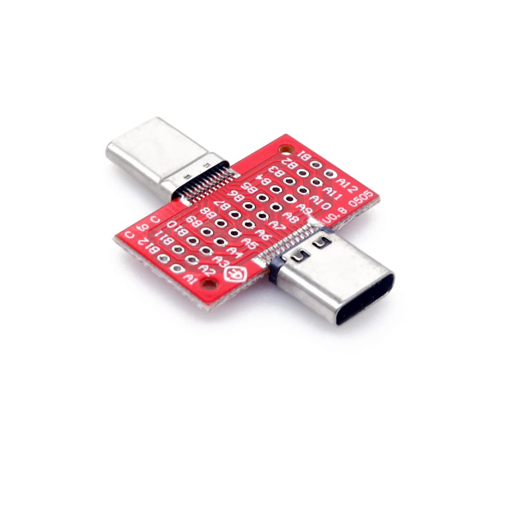
Figure 1: Treedix USB 3.1 Type-C Male to Female Test Board.
2. Safety Information
Please read and understand all safety instructions before using this product. Failure to follow these instructions may result in electric shock, fire, or serious injury.
- Electrical Safety: This product is an electronic component. Handle with care to avoid electrostatic discharge. Do not connect to power sources exceeding specified voltage limits.
- Handling: Avoid bending or applying excessive force to the board or connectors. This can damage the internal circuitry.
- Environment: Use in a dry environment. Avoid exposure to moisture, extreme temperatures, or corrosive substances.
- Children: Keep out of reach of children. This product contains small parts that could be a choking hazard.
- Modifications: Do not attempt to modify or disassemble the product beyond its intended use. Unauthorized modifications may void the warranty and pose safety risks.
3. Package Contents
Verify that all items are present upon opening the package:
- 1x Treedix USB 3.1 Type-C Male to Female Test Board (Model 0035)
- (Optional, depending on kit) Jumper wires or pin headers for connection.
Video 1: Unboxing and overview of the USB 3.1 Type-C Male to Female Test Board.
4. Setup
The Treedix USB 3.1 Type-C Test Board is designed for straightforward integration into your testing or prototyping environment.
- Identify Connectors: The board features a USB Type-C male connector on one side and a USB Type-C female connector on the other, allowing for inline testing or extension.
- Pin Header Connection: The board provides double rows of holes (standard 2.0 specification pin header 12*2) with a spacing of 2.2mm and an aperture of 0.7mm. These holes are designed for soldering pin headers or connecting jumper wires to access individual pins of the USB Type-C interface.
- Secure Mounting: The PCB board includes positioning holes, making it easy to fix and secure in a breadboard, custom enclosure, or test jig.
- Prepare Connections: Depending on your application, solder appropriate wires or pin headers to the desired test points on the board. Refer to the pinout diagram for correct identification of each pin.

Figure 2: Top view of the test board, highlighting the pin header connection points.

Figure 3: Bottom view of the test board, showing the male and female Type-C connectors.
5. Operating Instructions
This test board acts as a passive breakout board, providing access to the USB Type-C pins. It does not require external power for its basic function.
- Connect Cable: Plug your USB Type-C cable into the female port of the test board.
- Connect Device/Source: Plug the male port of the test board into your device (e.g., tablet, phone, USB data line tester) or power source.
- Access Pins: Use jumper wires or probes connected to the pin headers to monitor signals, inject signals, or perform continuity tests on specific USB Type-C pins.
- Data Transfer & Power: The board supports USB 3.1 standard transmission rates up to 10Gbps, allowing for high-speed data transfer and power delivery testing, provided the connected cable and devices also support these standards.

Figure 4: The test board in use, connected to a smartphone for power or data transfer.
Video 2: Demonstration of connecting the Type-C 24-pin male and female breakout board.
USB Type-C Pinout Diagram
Understanding the pin assignments is crucial for effective use of the test board.

Figure 5: USB Type-C 24-pin pinout diagram for reference during testing and prototyping.
| Pin Name | Function |
|---|---|
| GND | Ground |
| TX1+, TX1- | USB 3.1 Transmit Differential Pair 1 |
| RX1+, RX1- | USB 3.1 Receive Differential Pair 1 |
| VBUS | Power (5V) |
| CC1, CC2 | Configuration Channel (for orientation, power delivery, alternate modes) |
| D+, D- | USB 2.0 Data Lines |
| SBU1, SBU2 | Sideband Use (for alternate modes like DisplayPort) |
6. Maintenance
To ensure the longevity and reliable performance of your Treedix USB 3.1 Type-C Test Board, follow these maintenance guidelines:
- Cleaning: Use a soft, dry cloth to clean the board. For stubborn dirt, a cotton swab lightly dampened with isopropyl alcohol can be used. Ensure the board is completely dry before use.
- Storage: Store the board in a cool, dry place, away from direct sunlight and extreme temperatures. Keep it in an anti-static bag or container to prevent electrostatic discharge damage.
- Inspection: Periodically inspect the connectors and solder points for any signs of damage, corrosion, or loose connections.
- Avoid Contaminants: Prevent dust, liquids, and metal particles from coming into contact with the board, especially the exposed pins.
7. Troubleshooting
If you encounter issues while using the Treedix USB 3.1 Type-C Test Board, consider the following common problems and solutions:
| Problem | Possible Cause | Solution |
|---|---|---|
| No signal/power detected | Loose connection; faulty cable; incorrect pin connection. | Ensure all connections are secure. Test with a known good cable. Verify pin connections against the pinout diagram. |
| Intermittent connection | Damaged connector; cold solder joint; cable movement. | Inspect connectors for physical damage. Re-solder any suspicious joints. Secure the board and cables to prevent movement. |
| Slow data transfer speed | Cable not supporting USB 3.1; connected device limitation. | Ensure you are using a USB 3.1 compatible cable and that both connected devices support USB 3.1 speeds. |
| Board not fitting properly | Incorrect orientation; debris in port. | USB Type-C is reversible, but ensure the male connector is fully inserted. Check for any obstructions in the ports. |
8. Specifications
| Feature | Detail |
|---|---|
| Product Type | USB 3.1 Type-C Male to Female Test Board |
| Model Number | 0035 |
| Connectors | 1x USB Type-C Male, 1x USB Type-C Female |
| Pin Count | 24-Pin (full Type-C interface) |
| Pin Header Type | Double row, standard 2.0 specification (12x2) |
| Pin Spacing | 2.2mm |
| Aperture | 0.7mm |
| Data Transmission | USB 3.1 (up to 10Gbps) |
| Insertion Times | 3000-5000 times |
| PCB Board Size | 14 x 25mm (0.55 x 0.98in) |
| Manufacturer | Treedix |
9. Warranty and Support
Warranty Information: Treedix products are covered by a standard manufacturer's warranty against defects in materials and workmanship. Please refer to the official Treedix website or your purchase documentation for specific warranty terms and duration.
Customer Support: For technical assistance, troubleshooting, or warranty claims, please contact Treedix customer support through their official website or the retailer where the product was purchased.
Official Website: www.treedix.com


