
UeeVii CPE453
Contents
UeeVii CPE453 Wireless Bridge User Manual
Outdoor Point to Point Wireless Bridge System
1. Introduction
The UeeVii CPE453 Wireless Bridge system provides a robust and reliable solution for extending network connectivity over long distances without the need for extensive cabling. This outdoor point-to-point wireless bridge is designed for various applications, including expanding home networks to secondary buildings, extending Starlink internet access, and establishing surveillance camera networks.
It operates on the 5.8GHz frequency band and features a built-in dual-polarized 14dBi high-gain directional antenna, enabling stable transmission up to 3 kilometers with a clear line of sight. The system is IP65-rated, ensuring durability and performance in various outdoor weather conditions.
2. Package Contents
Please verify that all components are present and in good condition upon opening the package.
- One (1) set of UeeVii CPE453 Wireless Bridges (includes two CPE units)
- Two (2) Wireless Bridge Bracket Mounts
- Two (2) PoE Adapters
- Two (2) Ethernet Cables
- User Manual (this document)

Image: The UeeVii CPE453 wireless bridge units, shown with their included mounting brackets, illustrate the primary components of the wireless bridge system.
3. Key Features
- High-Speed Wireless Transmission: Supports 5.8GHz frequency band with up to 100Mbps data transfer rates.
- Long-Range Connectivity: Achieves up to 3KM wireless transmission distance with clear line of sight, utilizing a built-in dual-polarized 14dBi high-gain directional antenna.
- Master/Slave Configuration: Easy setup with dedicated M/S (Master/Slave) switch for defining roles.
- Dialing Pairing: Simplified pairing process using numerical dials on each unit.
- Outdoor Durability: IP65 level weatherproof design ensures reliable operation in various outdoor environments, including rain, snow, and extreme temperatures.
- Versatile Applications: Ideal for extending networks to remote buildings (garages, barns), Starlink network expansion, and establishing surveillance camera networks.
- Power over Ethernet (PoE): Simplifies installation by delivering power and data over a single Ethernet cable.

Image: This image illustrates the core performance specifications of the UeeVii CPE453, emphasizing its 5.8GHz operating frequency and 100Mbps data transfer capability, crucial for stable and fast wireless bridging.

Image: The UeeVii CPE453 unit is depicted with icons representing its IP65 weatherproof rating, indicating resistance to lightning, rain, snow, and extreme cold. This highlights its suitability for outdoor deployment in various weather conditions.
4. Setup Guide
4.1. Pre-installation Checklist
- Ensure you have two CPE453 units, two PoE adapters, and two Ethernet cables.
- Identify suitable mounting locations for both units, ensuring a clear line of sight between them for optimal performance. Obstructions like walls, trees, or large buildings can significantly degrade signal quality.
- Have necessary tools for mounting (e.g., drill, screwdriver, level).
4.2. Master/Slave Configuration
One CPE unit must be configured as the Master Bridge and the other as the Slave Bridge. This is done using the M/S switch on each unit.
- For the Master Bridge unit, set the M/S switch to 'M'.
- For the Slave Bridge unit, set the M/S switch to 'S'.

Image: This diagram illustrates the setup for Master and Slave bridge modes. The Master bridge connects to your network source (e.g., router, switch, DVR), while the Slave bridge connects to the remote device (e.g., IP camera, computer).
4.3. Dialing Pairing
After setting the Master/Slave roles, you need to pair the devices by setting the same numerical code on both units.
- On both the Master and Slave units, locate the dialing switch.
- Set the dialing switch on both units to the same number (e.g., '1', '2', '3', etc.). This number acts as a pairing code.
- Ensure the numbers match exactly for successful pairing.

Image: This image demonstrates the dialing pairing process. Both the Master and Slave units have a numerical dial that must be set to the same number to establish a wireless connection between them.
4.4. Physical Installation and Connection
- Mounting: Use the provided brackets to securely mount the CPE units in their chosen outdoor locations. Ensure they are oriented towards each other with a clear line of sight. The anti-slip gear design on the brackets helps maintain the desired angle.
- Power Connection: Connect an Ethernet cable from the "PoE" port of the PoE adapter to the "LAN 1/PoE" port on the CPE unit.
- Network Connection (Master): Connect an Ethernet cable from the "LAN" port of the Master unit's PoE adapter to your network device (e.g., router, switch, NVR/DVR).
- Network Connection (Slave): Connect an Ethernet cable from the "LAN" port of the Slave unit's PoE adapter to your remote device (e.g., IP camera, computer, access point).
- Power On: Plug the PoE adapters into a power outlet. The units will power on and attempt to establish a connection.

Image: This image provides two common application diagrams: extending a network to a second building and extending camera monitoring range. Both scenarios demonstrate the point-to-point connection using the Master and Slave CPE units and their respective PoE adapters.

Image: Detailed view of the mounting bracket, highlighting its dimensions and the anti-slip gear design. This design ensures the CPE unit remains securely positioned after installation, preventing slippage due to wind or vibration.
5. Operating Instructions
5.1. Connection Status Indicators
Once powered on, observe the LED indicators on the CPE units to confirm connection status:
- Power LED: Indicates the unit is powered on.
- Signal Strength LEDs: Multiple LEDs indicate the strength of the wireless signal between the Master and Slave units. More lit LEDs mean a stronger connection. Adjust alignment if signal is weak.
- LAN LEDs: Indicate active Ethernet connections on the LAN ports.
5.2. Optimizing Performance
- Clear Line of Sight: Ensure there are no physical obstructions (trees, buildings, hills) between the two CPE units. Even partial obstructions can significantly reduce performance.
- Precise Alignment: Carefully align both units to point directly at each other. Use the signal strength LEDs as a guide for fine-tuning alignment.
- Interference: While operating on 5.8GHz, which is less congested than 2.4GHz, other wireless devices or strong electromagnetic fields can cause interference. Try to minimize such sources near the units.
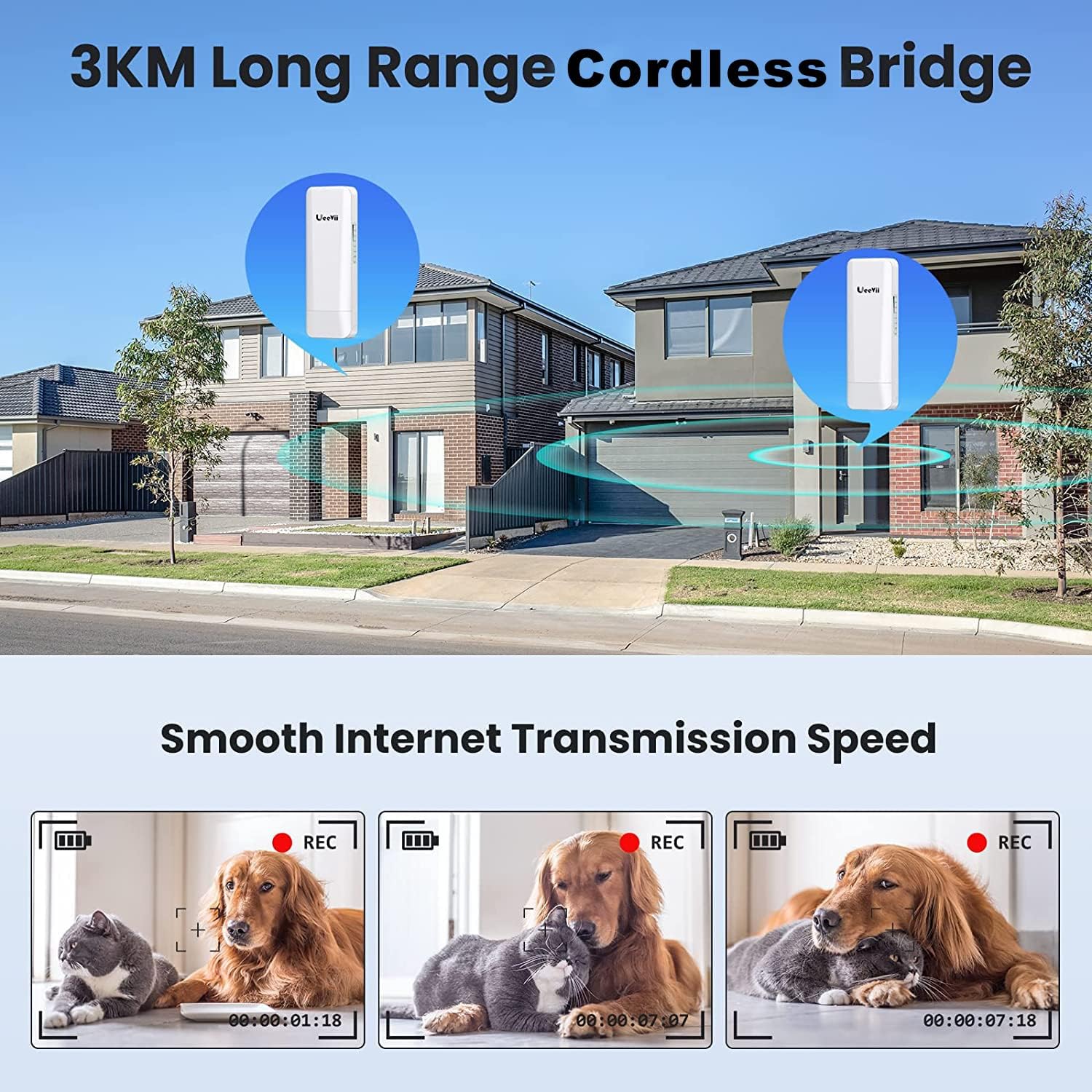
Image: This visual emphasizes the 3KM long-range capability of the wireless bridge and its ability to provide smooth internet transmission, as demonstrated by the clear video feeds of pets, suggesting reliable data transfer for surveillance or general network use.
6. Maintenance
The UeeVii CPE453 is designed for minimal maintenance due to its robust outdoor rating. However, periodic checks can ensure long-term optimal performance.
- Physical Inspection: Periodically inspect the units and mounting brackets for any physical damage, loose connections, or signs of wear.
- Clear Line of Sight: Ensure that vegetation growth (trees, bushes) or new structures do not obstruct the line of sight between the two units. Trim foliage if necessary.
- Cleaning: If units become excessively dirty, gently wipe them with a damp cloth. Do not use harsh chemicals or abrasive cleaners. Ensure all ports are free of debris.
- Firmware Updates: Check the UeeVii official website periodically for any available firmware updates. Follow the instructions provided with the update carefully.
7. Troubleshooting
| Problem | Possible Cause | Solution |
|---|---|---|
| No Power / Unit not turning on | No power from outlet; Faulty PoE adapter; Loose cable connection. | Check power outlet; Verify PoE adapter is working; Ensure Ethernet cables are securely connected. |
| No Wireless Link / Weak Signal | No clear line of sight; Misalignment; Incorrect Master/Slave setting; Mismatched dialing code. | Ensure clear line of sight; Re-align units using signal LEDs; Verify M/S switch is correct; Confirm dialing codes match. |
| Network Connectivity Issues | Incorrect network configuration; Faulty Ethernet cable; IP address conflict. | Check network settings on connected devices; Test Ethernet cables; Ensure no IP conflicts on your network. |
| Slow Speed / Intermittent Connection | Partial obstruction; Interference; Poor alignment. | Clear any obstructions; Check for sources of interference; Re-align units for stronger signal. |
8. Specifications
| Feature | Detail |
|---|---|
| Model Name | CPE453 |
| Brand | UeeVii |
| Wireless Standard | 802.11ax |
| Frequency Band | 5.8GHz (Dual-Band capable, though primary operation is 5.8G for bridge) |
| Antenna Type | Fixed, Dual-polarized 14dBi High-Gain Directional Antenna |
| Transmission Distance | Up to 3KM (clear line of sight) |
| Weather Resistance | IP65 Level Weatherproof |
| Connectivity Technology | Wi-Fi, Power over Ethernet (PoE) |
| Special Feature | WPS (Wireless Protected Setup) - Note: While listed, the primary pairing method is dialing. WPS may be for advanced configuration. |
| Compatible Devices | Personal Computer, IP Cameras, Network Video Recorders (NVRs), Routers, Switches |
| Recommended Uses | Business, Home, Surveillance, Network Extension |
9. Warranty and Support
UeeVii products are typically covered by a manufacturer's warranty. For specific warranty terms, duration, and conditions, please refer to the warranty card included with your product or visit the official UeeVii website.
For technical support, troubleshooting assistance, or inquiries regarding your UeeVii CPE453 Wireless Bridge, please contact UeeVii customer service through their official channels. Contact information can usually be found on the product packaging, the official website, or the purchase platform.
When contacting support, please have your product model (CPE453) and purchase details readily available.
Documents and downloads
Ask a question about this manual
Ask about setup, troubleshooting, compatibility, parts, safety, or missing instructions. Manuals+ will review the question and use this page’s manual context to help answer it.