1. Introduction
This manual provides comprehensive instructions for the installation, operation, and maintenance of the Gdrasuya10 YL568K Variable Frequency Drive (VFD). This VFD is designed to control the speed of three-phase AC motors by varying the frequency and voltage of the power supplied to the motor. It is suitable for a wide range of industrial and domestic applications requiring precise motor speed control.
Important Safety Notes
- Environment: Avoid using the inverter in environments with high humidity, water mist, or falling metal debris, as this may cause a short circuit and damage the unit.
- Motor Power: Ensure that the motor power does not exceed TWICE the rated power of this VFD (1.5KW / 2HP). Exceeding this limit can lead to malfunction or damage.
- Read Manual: Always read this operating manual completely before attempting any installation, operation, or maintenance. Pay particular attention to all safety instructions provided herein.
- Electrical Safety: Do not connect AC power to the output terminals (U, V, W). Do not contact any internal components unless the charge lamp is turned off and the unit is fully discharged. Always ensure power is disconnected before working on the VFD.
2. Product Overview

Figure 2.1: Angled view of the Gdrasuya10 YL568K Variable Frequency Drive, showcasing its compact design and control panel.

Figure 2.2: The VFD unit displaying its physical dimensions: 11cm (4.33in) width, 8.5cm (3.3in) depth, and 14.5cm (5.71in) height.
The YL568K VFD is a robust and reliable frequency converter designed for precise motor control. It features a user-friendly interface with a digital display and intuitive buttons for easy operation. Its compact size allows for flexible installation in various setups.
3. Specifications
| Parameter | Value |
|---|---|
| Model | YL568K |
| Color | Black |
| Material | ABS |
| Input Voltage | 220V |
| Output Voltage | 220V |
| Rated Current | 7A |
| Suitable Motor Power | 1.5KW (2HP) |
| Power Supply Phase | Single Phase |
| Output Phase | 3 Phase |
| DC Power Supply Type | Voltage Type |
| Net Weight | 1kg / 2.2lbs |
| Gross Weight | 1.2kg / 2.7lbs |
| Product Size (L*W*H) | 11cm * 8.5cm * 14.5cm (4.33in * 3.3in * 5.71in) |
4. Key Features
- 8-Way Protective System: Includes comprehensive protection against over voltage, over current, overload, overheating, stalling, and open phase to ensure safe and reliable operation. Supports external braking resistor for rapid acceleration/deceleration control.
- High-Quality Motherboard: The motherboard surface is coated with tri-proof paint, providing insulation, anti-leakage, dust-proof, anti-corrosion, and anti-aging properties, enhancing durability and environmental resistance.
- Remote Control Capability: Remote operation is possible via an external extension panel, allowing control from up to 50m (164ft) away, increasing operational flexibility and safety.
- Wide Application Range: Versatile for use in various CNC machines, mechanical equipment, household appliances (e.g., washing machines, sewing machines), machine tool spindles, and more.
- Easy to Operate: Features a user-friendly and well-laid-out keyboard with a clear digital display, making operation visual and straightforward.
5. Setup and Installation
5.1 Wiring Diagram and Terminals

Figure 5.1: Close-up view of the VFD's control panel and wiring terminals, showing input (RST), output (UVW), and control (24V, 10V, AI1, GND, DI1-DI5, TA, TB, TC, AO1, GND, FM, A+, B-) connections.
Proper wiring is crucial for the safe and correct operation of the VFD. Refer to the diagram above and follow these guidelines:
- Power Input (R, S, T): Connect the single-phase 220V AC power supply to the R and T terminals. The S terminal may not be used for single-phase input. Ensure proper grounding to the 'PB' or 'PE' terminal if available, or a dedicated ground terminal.
- Motor Output (U, V, W): Connect the three-phase motor leads to the U, V, and W output terminals. Ensure correct phase sequence for desired motor rotation.
- Control Terminals:
- 24V, 10V, GND: Power supply for external control components.
- AI1, AO1: Analog input/output for speed reference (e.g., potentiometer) or monitoring.
- DI1-DI5: Digital inputs for various control functions (e.g., start, stop, multi-speed).
- TA, TB, TC: Relay output terminals for status indication or external control.
- FM: Frequency meter output.
- A+, B-: RS485 communication terminals for remote control or monitoring.
- Braking Resistor: If an external braking resistor is required for fast deceleration, connect it to the appropriate terminals (refer to the full manual for specific connections, typically P+ and PB).
- Safety First: Always ensure power is disconnected before making or changing any wiring connections. Verify all connections are secure and correct before applying power.
5.2 Mounting
Mount the VFD in a clean, dry, and well-ventilated area, away from direct sunlight, excessive heat, humidity, and corrosive gases. Ensure sufficient clearance around the unit for proper heat dissipation. Use appropriate screws and mounting hardware to secure the VFD firmly to a stable surface.
6. Operating Instructions
6.1 Control Panel Overview

Figure 6.1: Top-down view of the VFD's control panel, highlighting the digital display, rotary knob, and function buttons.
The control panel consists of a digital display and several function buttons:
- Digital Display: Shows current frequency, output voltage, current, and various parameter settings.
- PROG (Program): Enters/exits parameter setting mode.
- UP (▲): Increases parameter values or navigates up through menus.
- DOWN (▼): Decreases parameter values or navigates down through menus.
- SHIFT (Shift): Moves the cursor during parameter editing or shifts display modes.
- ENTER (Enter): Confirms parameter settings or enters sub-menus.
- RUN (Run): Starts the motor.
- STOP (Stop): Stops the motor.
- Rotary Knob: Used for fine adjustment of frequency or parameter values.
6.2 Basic Operation
- Power On: After ensuring all wiring is correct and secure, apply power to the VFD. The digital display will light up.
- Set Frequency:
- In normal display mode, use the UP/DOWN buttons or the rotary knob to adjust the desired output frequency.
- Alternatively, press PROG to enter parameter mode, navigate to the frequency setting parameter (e.g., F0.01), adjust the value, and press ENTER to confirm.
- Start Motor: Press the RUN button. The motor will start accelerating to the set frequency.
- Stop Motor: Press the STOP button. The motor will decelerate and stop.
- Parameter Adjustment: To access advanced settings (e.g., acceleration/deceleration time, motor parameters), press the PROG button to enter the parameter menu. Use UP/DOWN to navigate, SHIFT to move the cursor, and ENTER to select and confirm. Refer to the detailed parameter list in the full English manual for specific functions.
7. Maintenance
Regular maintenance ensures the longevity and optimal performance of your VFD.
- Cleaning: Periodically clean the VFD's exterior with a soft, dry cloth. Ensure ventilation openings are free from dust and debris. Do not use liquid cleaners or solvents.
- Environmental Check: Regularly inspect the operating environment to ensure it remains free from excessive humidity, water mist, metal dust, and corrosive substances.
- Connection Check: Periodically check all wiring connections for tightness and signs of wear or corrosion. Loose connections can lead to overheating and malfunction.
- Cooling Fan: Ensure the cooling fan (if present) is operating correctly and not obstructed. Clean fan blades if necessary.
- Professional Inspection: For internal inspection or complex issues, it is recommended to consult a qualified technician.
8. Troubleshooting
This section provides solutions to common issues you might encounter. For more complex problems, refer to the detailed troubleshooting guide in the complete manual or contact technical support.
| Problem | Possible Cause | Solution |
|---|---|---|
| VFD does not power on. | No input power; loose power connections; internal fuse blown. | Check power supply; verify all power wiring; consult technician for fuse replacement. |
| Motor does not run. | Incorrect wiring (U,V,W); VFD in stop mode; frequency set to 0; motor fault. | Verify motor wiring; press RUN button; increase frequency setting; check motor for issues. |
| Overload error displayed. | Motor overloaded; VFD capacity too small for motor; acceleration time too short. | Reduce motor load; ensure VFD matches motor power (1.5KW max); increase acceleration time parameter. |
| Overvoltage/Undervoltage error. | Input voltage outside acceptable range; sudden load changes. | Check input power supply voltage; ensure stable power source; consider braking resistor for rapid deceleration. |
| Motor runs in wrong direction. | Incorrect motor phase sequence. | Swap any two of the U, V, W output wires to the motor (after disconnecting power). |
9. Applications
The Gdrasuya10 YL568K Variable Frequency Drive is highly versatile and suitable for a wide array of applications requiring precise speed control of three-phase motors. Common applications include:
- Spindle Motors: For CNC machines and other precision machining equipment.
- Drill Presses: Enabling variable speed for different materials and drilling operations.
- HVAC Systems: Controlling fan and pump speeds for energy efficiency and precise climate control.
- Lathes and Milling Machines: Providing adjustable cutting speeds.
- Production Lines and Conveyors: For controlled material handling and processing.
- Pumps and Compressors: Optimizing flow and pressure based on demand.
- General Three-Phase Motors: Any application where variable speed control is beneficial.
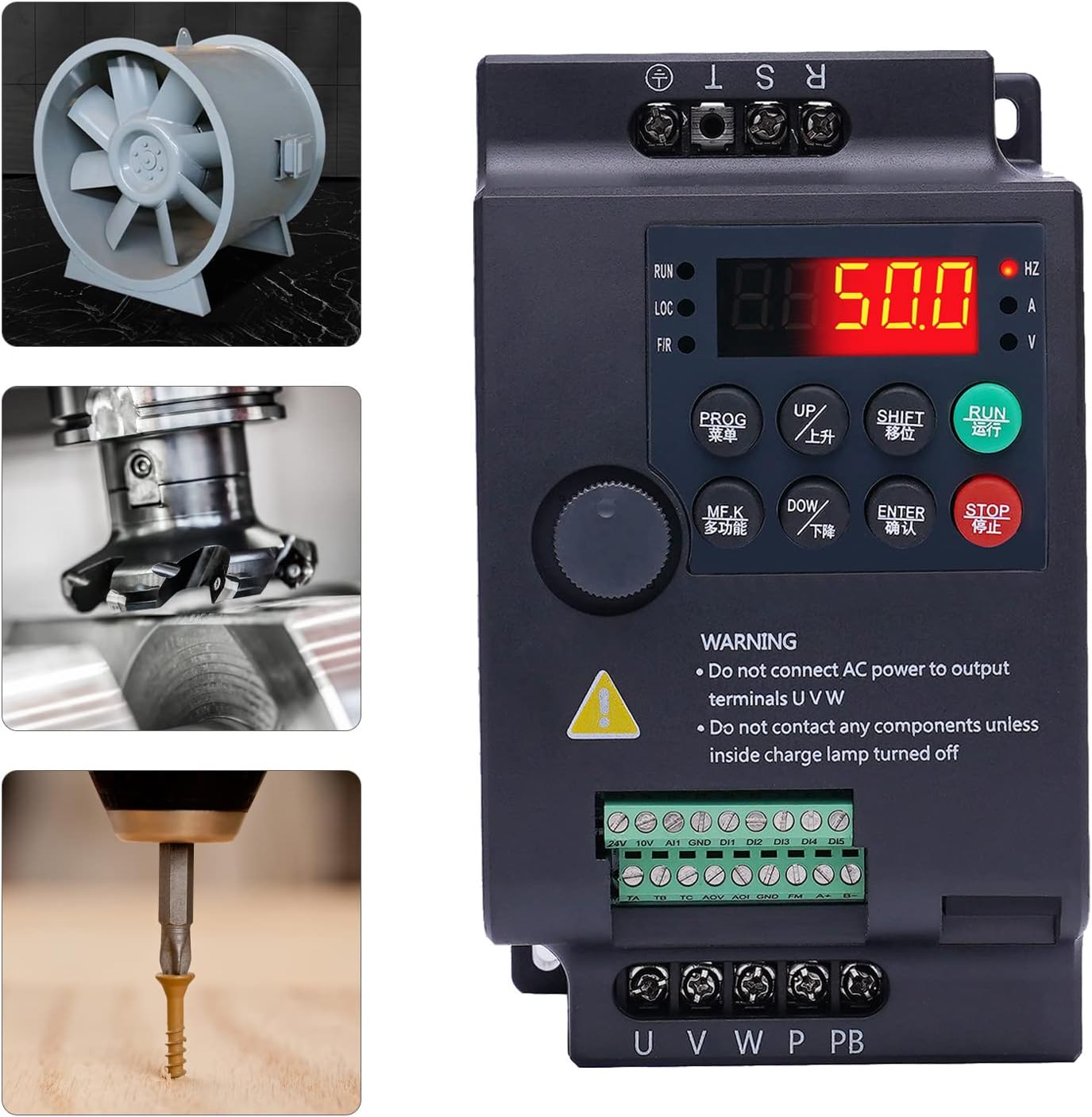
Figure 9.1: Visual examples of the VFD's application in controlling a fan, a milling machine, and a drill press.
10. Warranty and Support
This product comes with a standard manufacturer's warranty. Please refer to the warranty card included in your package for specific terms and conditions, including warranty period and coverage details. Keep your purchase receipt as proof of purchase.
For technical support, troubleshooting assistance, or warranty claims, please contact Gdrasuya10 customer service through the retailer where you purchased the product or visit the official Gdrasuya10 store page on Amazon for contact information. When contacting support, please have your product model number (YL568K) and purchase details ready.
Online Support: Visit the Gdrasuya10 Store on Amazon

