
1. Introduction
Thank you for choosing the Assark Digital Multimeter Model 620A. This compact and versatile instrument is designed for safe and accurate troubleshooting of various electrical problems in automotive and household settings. It is an ideal tool for DIY enthusiasts and professionals alike, offering measurements for AC/DC voltage, AC/DC current, resistance, continuity, diode, and transistor testing.
Please read this manual thoroughly before operating the device to ensure safe and proper use. Keep this manual for future reference.
2. Safety Information
WARNING: To avoid possible electric shock or personal injury, and to avoid possible damage to the meter or to the equipment under test, follow these safety rules:
- Always ensure the multimeter is set to the correct range before testing.
- Do not apply more than the rated voltage, as marked on the meter, between the terminals or between any terminal and earth ground. The maximum voltage for this device is 600V AC/DC.
- Use extreme caution when working with voltages above 60V DC or 30V AC RMS. Such voltages pose a shock hazard.
- Disconnect the test leads from the circuit before changing functions or ranges.
- Do not use the meter if it appears damaged or if the insulation on the test leads is damaged.
- Always use the proper terminals, function, and range for your measurements.
- Ensure the battery compartment is securely closed before operation.
- This meter cannot measure AC current.

Figure 2.1: Safety Design with Fuses. The multimeter features two built-in fuses (250mA, 250V and 10A, 250V) providing overload protection for all measurement ranges, enhancing user safety.
3. Product Overview
The Assark Digital Multimeter 620A is a compact and robust device designed for ease of use and durability. It features a clear LCD display and a rotary switch for selecting functions.

Figure 3.1: Multimeter Components. This image highlights the key components of the multimeter: the 2000-count LCD display, backlight button, data hold button, function/range selector switch, 10A input jack, COM jack, and VΩmA input jack.
Key Features:
- LCD Display: 3 ½ digit (1999 count) backlit LCD for clear readings in various lighting conditions.
- Function/Range Selector: Rotary switch to select desired measurement type and range.
- Data Hold Button: Freezes the displayed reading for convenient recording.
- Backlight Button: Activates the display backlight for improved visibility in low-light environments.
- Protective Case: Durable, removable rubber cover provides protection against drops and light impacts, and includes a built-in foldable kickstand for hands-free operation.

Figure 3.2: Compact Design. The multimeter is designed to fit comfortably in your hand, with dimensions of approximately 11.8 cm (4.6 in) in height, 7.1 cm (2.8 in) in width, and 3.1 cm (1.2 in) in thickness, making it highly portable.
4. Setup
4.1. Package Contents
Before first use, please verify that all items are present and undamaged:
- 1 x Assark 620A Digital Multimeter
- 1 x User Manual
- 1 Pair of Multimeter Test Leads (Red and Black)
- 2 x AAA 1.5V Batteries
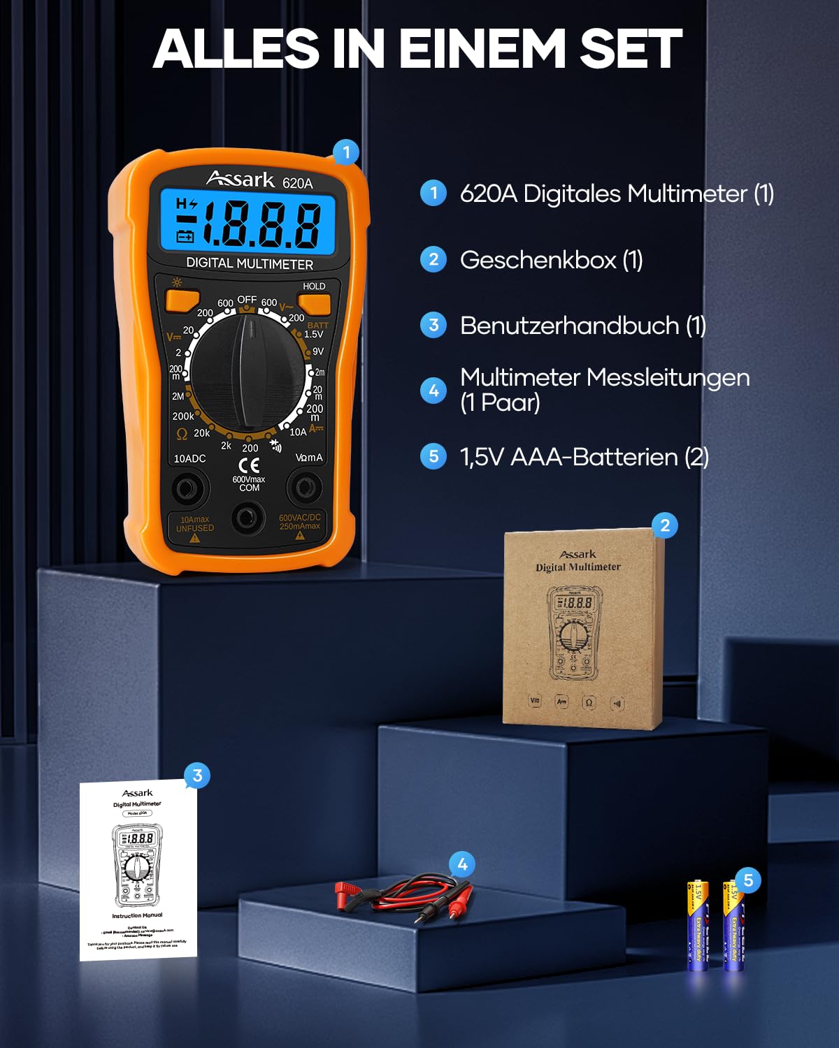
Figure 4.1: Complete Set. The package includes the 620A Digital Multimeter, a gift box, user manual, a pair of test leads, and two 1.5V AAA batteries, ensuring it's ready for immediate use.
4.2. Battery Installation
The multimeter requires two AAA 1.5V batteries (included). To install or replace batteries:
- Ensure the multimeter is turned OFF.
- Locate the battery compartment on the back of the unit.
- Unscrew the battery compartment cover using a Phillips head screwdriver.
- Insert the two AAA batteries, observing the correct polarity (+ and -) as indicated inside the compartment.
- Replace the battery compartment cover and secure it with the screw.
Note: The multimeter supports low battery indication. Replace batteries when the low battery indicator appears on the display.
5. Operating Instructions
Before taking any measurements, ensure the test leads are securely plugged into the correct input jacks. The black lead always connects to the "COM" (common) jack. The red lead connects to the "VΩmA" jack for voltage, resistance, and small current measurements, or to the "10A" jack for large current measurements.

Figure 5.1: Various Measurement Modes. The multimeter supports a range of functions including AC/DC voltage, DC current, resistance, diode testing, continuity testing, and battery testing, making it suitable for precise troubleshooting in household and automotive electrical systems.
5.1. DC Voltage Measurement (V=)
- Insert the red test lead into the "VΩmA" jack and the black test lead into the "COM" jack.
- Turn the rotary switch to the desired DC Voltage range (e.g., 200mV, 2V, 20V, 200V, 600V). If the voltage is unknown, start with the highest range and work downwards.
- Connect the test leads across the component or circuit to be measured, observing polarity.
- Read the voltage value on the LCD display.

Figure 5.2: Voltage Measurement. The top panel shows the multimeter measuring DC voltage from a 9V battery, indicating an accuracy for DC voltage ranges such as 200mV/2V/20V/200V ±(0.5% + 2) and 600V ±(0.8% + 2). The bottom panel illustrates AC voltage measurement from a wall outlet, with accuracy for 200V/600V ±(1.2% + 10).
5.2. AC Voltage Measurement (V~)
- Insert the red test lead into the "VΩmA" jack and the black test lead into the "COM" jack.
- Turn the rotary switch to the desired AC Voltage range (e.g., 200V, 600V).
- Connect the test leads across the AC voltage source.
- Read the voltage value on the LCD display.
5.3. DC Current Measurement (A=)
- For currents up to 200mA, insert the red test lead into the "VΩmA" jack. For currents up to 10A, insert the red test lead into the "10A" jack. The black test lead always goes into the "COM" jack.
- Turn the rotary switch to the desired DC Current range (e.g., 200µA, 2mA, 20mA, 200mA, 10A).
- Open the circuit where current is to be measured and connect the meter in series with the load.
- Read the current value on the LCD display.
5.4. Resistance Measurement (Ω)
- Insert the red test lead into the "VΩmA" jack and the black test lead into the "COM" jack.
- Turn the rotary switch to the desired Resistance range (e.g., 200Ω, 2kΩ, 20kΩ, 200kΩ, 2MΩ, 60MΩ).
- Ensure the circuit is de-energized before measuring resistance.
- Connect the test leads across the resistor or component.
- Read the resistance value on the LCD display.

Figure 5.3: Resistance, Continuity, and Diode Testing. The top panel shows resistance measurement with accuracy for ranges like 200Ω/2kΩ/20kΩ/200kΩ ±(0.8% + 2) and 2MΩ ±(1.0% + 2). The bottom left panel illustrates continuity testing, which produces an audible beep for low resistance. The bottom right panel demonstrates diode testing, showing the forward voltage drop.
5.5. Continuity Test
- Insert the red test lead into the "VΩmA" jack and the black test lead into the "COM" jack.
- Turn the rotary switch to the Continuity position.
- Connect the test leads across the circuit or component.
- If the resistance is less than approximately 50Ω, the built-in buzzer will sound, indicating continuity.
5.6. Diode Test
- Insert the red test lead into the "VΩmA" jack and the black test lead into the "COM" jack.
- Turn the rotary switch to the Diode Test position.
- Connect the red test lead to the anode and the black test lead to the cathode of the diode.
- The display will show the forward voltage drop (in Volts). If the leads are reversed or the diode is open, "OL" (Overload) will be displayed.
5.7. Battery Test (BATT 1.5V / 9V)
- Insert the red test lead into the "VΩmA" jack and the black test lead into the "COM" jack.
- Turn the rotary switch to the "BATT 1.5V" or "BATT 9V" position, depending on the battery type.
- Connect the red test lead to the positive terminal and the black test lead to the negative terminal of the battery.
- Read the battery voltage on the LCD display. This function tests the battery under a specific impedance, providing a more accurate indication of its charge state than a simple voltage measurement.
5.8. Data Hold Function
Press the "HOLD" button to freeze the current reading on the display. Press it again to release the hold and resume live readings.
5.9. Backlight Function
Press the backlight button (sun symbol) to turn on the display backlight. Press it again to turn it off. The backlight improves visibility in dimly lit areas.
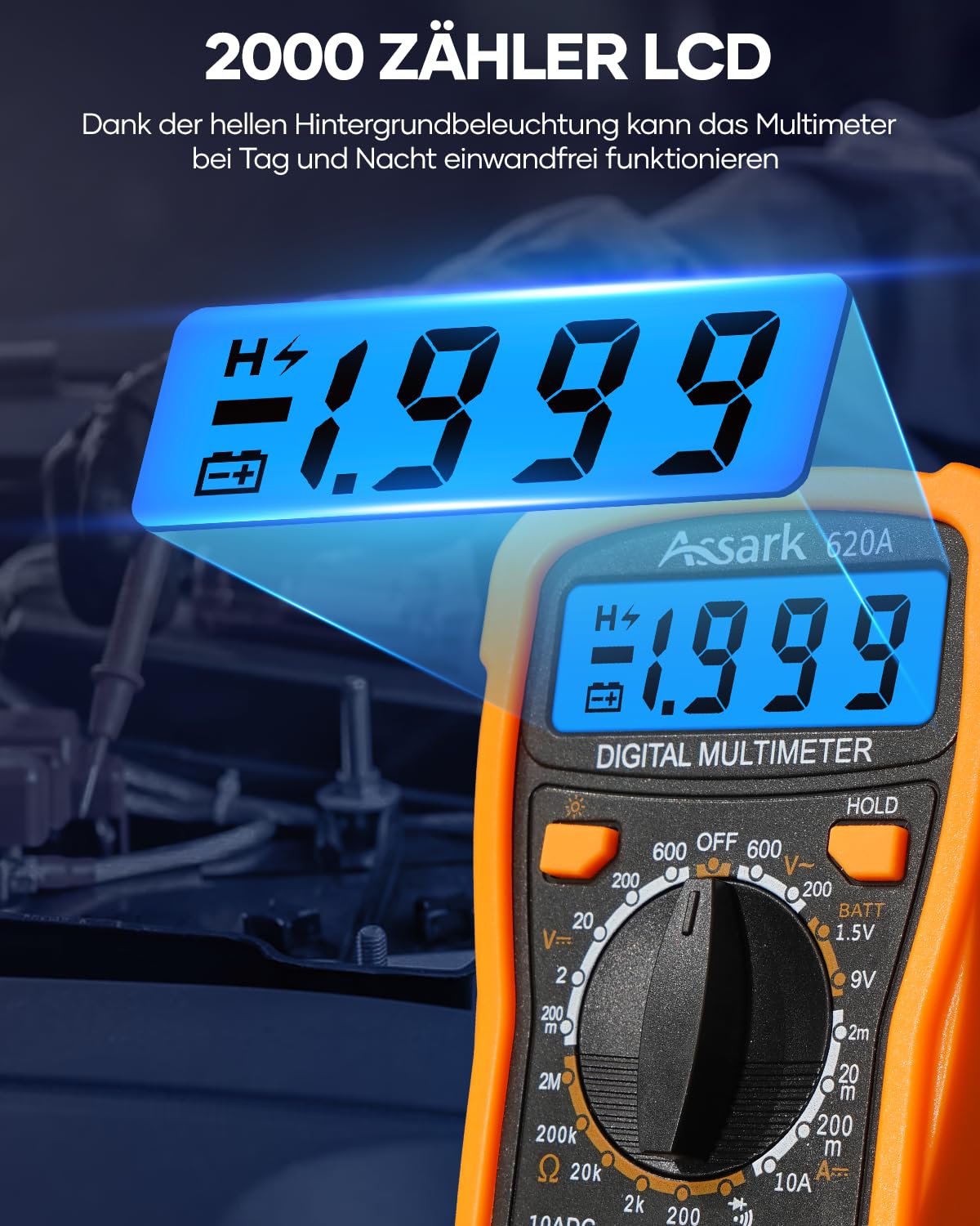
Figure 5.4: 2000 Count LCD Display. The bright backlit LCD display ensures clear readability of measurements, allowing the multimeter to function effectively both day and night.
6. Maintenance
6.1. Cleaning
Wipe the case with a damp cloth and mild detergent. Do not use abrasives or solvents. Keep the terminals free from dirt and moisture.
6.2. Storage
If the meter is not to be used for a long period, remove the batteries to prevent battery leakage and damage to the meter. Store the meter in a cool, dry place, away from direct sunlight and extreme temperatures.
6.3. Fuse Replacement
The multimeter is protected by two internal fuses. If the current measurement function stops working, the fuse may need replacement. Fuse replacement should only be performed by qualified personnel.
- F1 Fuse: 250mA/250V (for VΩmA jack)
- F2 Fuse: 10A/250V (for 10A jack)
Note: Always replace with a fuse of the same type and rating.
7. Troubleshooting
| Problem | Possible Cause | Solution |
|---|---|---|
| No display or dim display | Low battery or no battery installed. | Replace or install new AAA batteries. |
| "OL" (Overload) displayed | Measurement exceeds selected range or meter's maximum capacity. Open circuit in continuity/diode test. | Select a higher range. Check circuit connection. |
| Incorrect readings | Incorrect function/range selected. Poor test lead connection. Damaged test leads. | Verify function/range. Ensure leads are firmly connected. Inspect and replace damaged leads. |
| Current measurement not working | Blown fuse. | Replace the appropriate fuse (250mA or 10A). Refer to Section 6.3. |
| No continuity beep | Resistance is too high (above 50Ω) or open circuit. | Check the circuit for breaks or high resistance. |
8. Specifications
| Parameter | Value |
|---|---|
| Brand | Assark |
| Model Number | 620A |
| Display | 3 ½ digit LCD (1999 counts) with backlight |
| DC Voltage Range | 200mV / 2V / 20V / 200V / 600V |
| AC Voltage Range | 200V / 600V |
| DC Current Range | 200µA / 2mA / 20mA / 200mA / 10A |
| Resistance Range | 200Ω / 2kΩ / 20kΩ / 200kΩ / 2MΩ / 60MΩ |
| Continuity Test | Buzzer sounds if resistance < 50Ω |
| Diode Test | Yes |
| Battery Test | 1.5V, 9V |
| Power Source | 2 x AAA 1.5V Batteries (included) |
| Dimensions (L x W x H) | 8 x 8 x 3.5 cm (approx. 3.15 x 3.15 x 1.38 inches) |
| Weight | 200 grams (approx. 0.44 lbs) |
| Color | Yellow |
9. Warranty and Support
Assark products are manufactured to high-quality standards. This product is covered by a standard manufacturer's warranty against defects in materials and workmanship from the date of purchase. Please retain your proof of purchase for warranty claims.
For technical support, troubleshooting assistance, or warranty inquiries, please contact Assark customer service through the retailer's platform or the official Assark website. Provide your product model number (620A) and a detailed description of the issue to expedite support.
Note: Unauthorized disassembly or modification of the device will void the warranty.

