
ANENG CM81
ANENG CM81 Smart AC Clamp Meter User Manual
Model: CM81
1. Introduction
The ANENG CM81 Smart AC Clamp Meter is a versatile and portable electrical testing instrument designed for professional and home use. It offers a wide range of measurement functions, including AC/DC voltage, AC current, resistance, capacitance, and frequency. Its compact design, large backlit LCD, and additional features like NCV and a flashlight make it an essential tool for various electrical tasks.
This manual provides detailed instructions on how to safely and effectively use your CM81 Clamp Meter. Please read it thoroughly before operation.
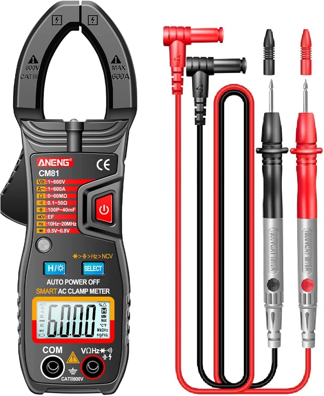
Figure 1.1: ANENG CM81 Smart AC Clamp Meter and included test leads.
2. Safety Information
Always adhere to basic safety precautions when using electrical testing equipment to reduce the risk of fire, electric shock, or personal injury. This meter is designed for safe operation, but it is crucial to follow all instructions and warnings.
- Do not exceed the maximum input value specified for any function.
- Do not use the meter if it is damaged or if the test leads are damaged.
- Exercise extreme caution when working with voltages above 60V DC or 30V AC RMS, as these pose a shock hazard.
- Always ensure the meter is set to the correct function and range before making measurements.
- Keep hands and fingers behind the probe barriers when testing.
- Replace batteries immediately when the low battery indicator appears.
- Do not operate the meter in explosive gas, vapor, or dust environments.
3. Product Features
- Multi-functional Clamp Meter: Measures AC/DC voltage, 600A AC current, resistance, capacitance, frequency, diode, and continuity.
- Real-time Temperature Display: Conveniently check the ambient temperature.
- Large Jaw Design: 36mm clamp head allows for non-contact measurement of single-strand wires without breaking the circuit.
- Convenient Data Review: Features a large LCD with backlight for clear readings and a data hold function to freeze measurements.
- Compact and Portable: Small body with full functionality, designed for easy one-handed operation.
- Durable Construction: Made from ABS material, providing good electrical insulation and drop resistance.
- Non-Contact Voltage (NCV) Test: Safely detect AC voltage without direct contact.
- Built-in Flashlight: Illuminates the measurement area in dark environments.
- Automatic Shutdown: Powers off automatically after 15 minutes of inactivity to save battery life.
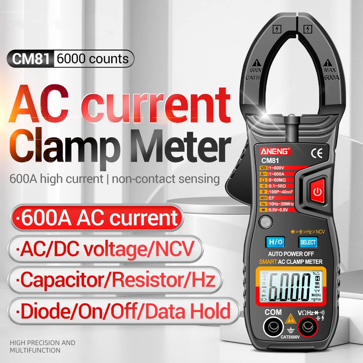
Figure 3.1: Key features of the CM81 Clamp Meter.
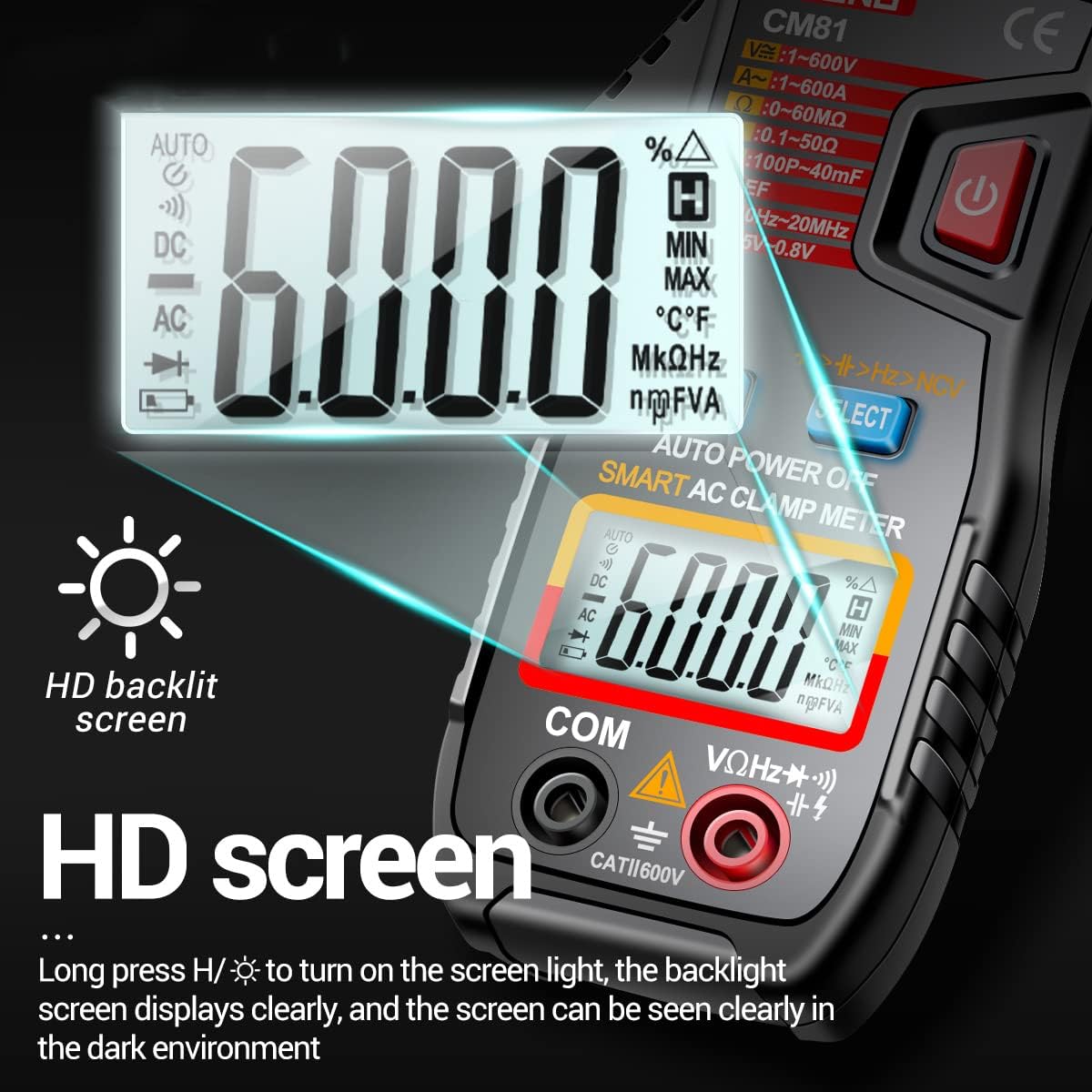
Figure 3.2: The CM81 features an HD backlit screen for clear visibility.
4. Specifications
| Parameter | Value |
|---|---|
| Color | Black (Red optional) |
| AC Voltage Range/Resolution/Accuracy | 1~600V / 0.001~1V / ±(1.5%+8) |
| DC Voltage Range/Resolution/Accuracy | 1~600V / 0.001~1V / ±(1.2%+5) |
| AC Current Range/Resolution/Accuracy | 1~600A / 1mA~0.1A / ±(2.8%+8) |
| Resistance Range/Resolution/Accuracy | 0~60MΩ / 0~10kΩ / ±(1.2%+5) |
| Capacitance Range/Resolution/Accuracy | 100pF~40mF / 1pF~10uF / ±(6%+10) |
| Frequency Range/Resolution/Accuracy | 10Hz~20MHz / 0.1Hz~10kHz / ±(4.0%+10) |
| Diode Test | Yes |
| Buzzer (Continuity) | Yes |
| Data Hold | Yes |
| Non-Contact Voltage (NCV) Test | Yes |
| Flashlight | Yes |
| Low Battery Indicator | Yes |
| Real-time Temperature Display | Yes |
| Range Selection | Auto Range |
| Automatic Power Off | 15 minutes |
| Display Screen | Backlit LCD |
| Maximum Display Count | 6000 counts |
| Power Source | 2 x 1.5V AAA Batteries (not included) |
| Jaw Opening Size | 36mm / 1.41 inches |
| Product Size | 185 x 65 x 32 mm / 7.28 x 2.56 x 1.26 inches |
| Product Weight | 136 grams / 4.80 ounces |
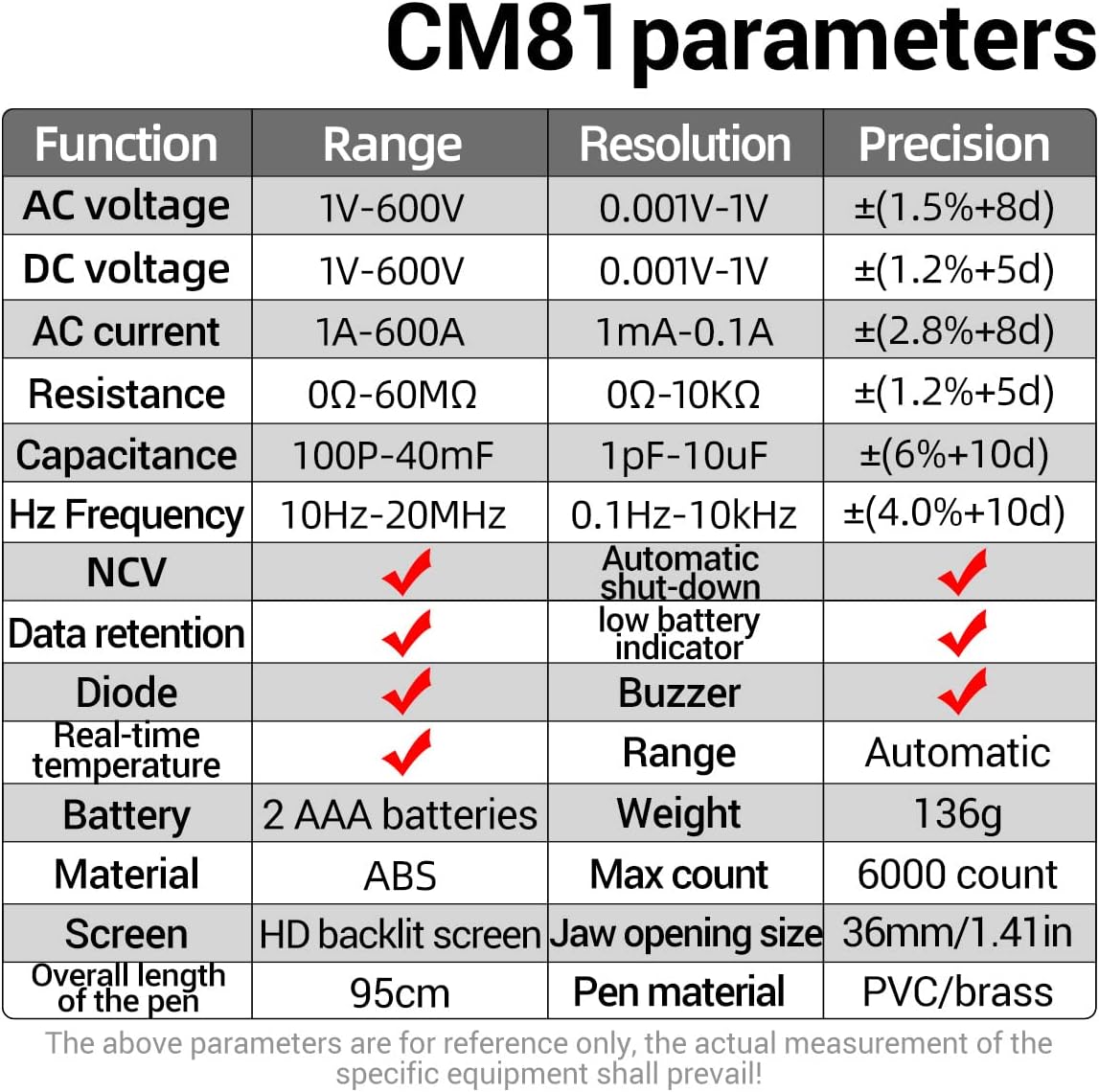
Figure 4.1: Detailed parameters of the CM81 Clamp Meter.
5. Setup
5.1 Battery Installation
- Locate the battery compartment cover on the back of the meter.
- Use a screwdriver to open the battery compartment.
- Insert two 1.5V AAA batteries, observing the correct polarity (+ and -).
- Replace the battery compartment cover and secure it with the screw.
5.2 Connecting Test Leads
For voltage, resistance, capacitance, frequency, diode, and continuity measurements, connect the test leads:
- Insert the red test lead into the "VΩHz" input jack.
- Insert the black test lead into the "COM" input jack.

Figure 5.1: Connecting test leads for various measurements.
6. Operating Instructions
6.1 Power On/Off
Press the red power button (U) to turn the meter on. The meter will automatically enter auto-ranging mode. To turn off the meter, press the power button again, or it will automatically shut down after 15 minutes of inactivity.

Figure 6.1: The CM81 features an automatic shut-down function to conserve battery life.
6.2 Function Selection
The CM81 features automatic identification for most common measurements (voltage, current, resistance, capacitance, continuity). Simply connect the test leads or clamp the wire, and the meter will attempt to identify the measurement type.
For specific functions or to cycle through modes within a category (e.g., AC/DC voltage), press the "SELECT" button.
6.3 AC Current Measurement (Clamp Function)
- Ensure the meter is in AC current mode (indicated by 'A~' on the display).
- Open the clamp jaws by pressing the trigger.
- Place the single conductor wire (not a power cord with multiple wires) to be measured within the jaws.
- Close the jaws completely. The current reading will appear on the display.
Note: The clamp function is designed to measure current on a single conductor. Measuring multiple wires (e.g., a standard power cord) will result in an inaccurate reading as the magnetic fields will cancel each other out.

Figure 6.2: Measuring AC current with the clamp function.
6.4 Voltage Measurement (AC/DC)
- Connect the red test lead to the "VΩHz" jack and the black test lead to the "COM" jack.
- Select the appropriate voltage mode (AC or DC) using the "SELECT" button if not automatically detected.
- Connect the test probes in parallel to the circuit or component you wish to measure.
- Read the voltage value on the display.
6.5 Resistance, Capacitance, Frequency, Diode, Continuity Measurement
- Connect the red test lead to the "VΩHz" jack and the black test lead to the "COM" jack.
- Press the "SELECT" button to cycle through these functions until the desired mode is active.
- Connect the test probes to the component or circuit.
- Read the measurement on the display. For continuity, a buzzer will sound if the resistance is below a certain threshold.
6.6 Non-Contact Voltage (NCV) Test
- Press the "H/⚡" button to activate NCV mode.
- Move the top of the clamp meter near the conductor or outlet.
- The meter will beep and the NCV indicator will light up if AC voltage is detected.
6.7 Flashlight Function
Long press the "H/⚡" button to turn on the built-in flashlight. Long press again to turn it off. This is useful for working in dimly lit areas.

Figure 6.3: Using the built-in flashlight for improved visibility.
6.8 Data Hold
Press the "H/⚡" button briefly to activate the Data Hold function. This will freeze the current reading on the display. Press the button again to release Data Hold and resume live readings.
7. Maintenance
7.1 Cleaning
Wipe the meter's casing with a damp cloth and mild detergent. Do not use abrasives or solvents. Keep the input terminals clean to ensure accurate measurements.
7.2 Battery Replacement
When the low battery indicator appears on the display, replace the batteries immediately to ensure accurate readings and proper operation. Refer to section 5.1 for battery installation instructions.
8. Troubleshooting
- Meter does not power on: Check battery installation and ensure batteries are not depleted.
- Inaccurate readings: Ensure test leads are properly connected, the correct function/range is selected, and batteries are not low. For current measurements, ensure only a single conductor is within the clamp jaws.
- Display shows "OL": This indicates an overload, meaning the measured value is outside the selected range. Switch to a higher range or ensure the input is within the meter's maximum specifications.
9. Package Contents
The ANENG CM81 Smart AC Clamp Meter package includes:
- 1 x ANENG CM81 Clamp Meter
- 2 x Test Leads (Red and Black)
- 1 x User Manual (English)

Figure 9.1: All items included in the ANENG CM81 package.
10. Warranty and Support
For warranty information and technical support, please refer to the contact details provided by your retailer or visit the official ANENG website. Keep your purchase receipt as proof of purchase for any warranty claims.
Related documentsCM81


Ask a question about this manual
Ask about setup, troubleshooting, compatibility, parts, safety, or missing instructions. Manuals+ will review the question and use this page’s manual context to help answer it.