1. Introduction and Overview
The UNI-T UT204PRO is a portable True RMS AC/DC clamp meter designed for accurate and reliable electrical measurements. This professional digital multimeter features a clear LCD display and offers a wide range of functions, making it suitable for use in laboratories, factories, and homes. It measures AC/DC current up to 600A, AC/DC voltage up to 600V, frequency, duty cycle, resistance, capacitance, and temperature. Additionally, it includes Non-Contact Voltage (NCV) detection, LIVE wire detection, and diode/continuity tests.
Key features include:
- True RMS Measurement: Provides accurate readings for non-sinusoidal waveforms.
- Multi-functionality: Measures AC/DC current, AC/DC voltage, frequency, duty cycle, resistance, capacitance, temperature, diode, and continuity.
- NCV and LIVE Detection: Enhances safety and ease of use for identifying live wires.
- Clear LCD Display: Features a backlight for visibility in low-light conditions.
- Safety Compliance: Meets EN61010-1 CAT II 600V / CAT III 300V safety standards.
- Automatic Power Off: Conserves battery life by automatically shutting down after 15 minutes of inactivity.
2. Safety Information
Always adhere to safety precautions when using electrical testing equipment. Failure to do so may result in electric shock, injury, or damage to the meter. This device complies with EN61010-1 CAT II 600V / CAT III 300V safety standards. Ensure you understand and follow all instructions.
- Do not use the meter if it appears damaged or if the test leads are compromised.
- Always ensure the function switch is set to the correct range before making measurements.
- Do not apply voltage or current that exceeds the maximum rated values for the meter.
- Exercise extreme caution when working with voltages above 30V AC RMS, 42V peak, or 60V DC, as these pose a shock hazard.
- When measuring current, ensure the circuit is de-energized before connecting or disconnecting the clamp meter.
- Replace batteries promptly when the low battery indicator appears.
- Wear appropriate personal protective equipment (PPE), such as safety glasses and insulated gloves, when performing electrical measurements.
3. Product Components
The UNI-T UT204PRO Clamp Meter is designed with user-friendly components for efficient operation.
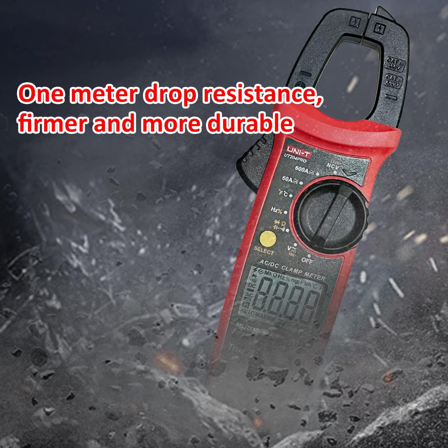
Figure 3.1: Detailed diagram of the UNI-T UT204PRO Clamp Meter, highlighting its jaws, hand guard, LED indicator, function scale knob, function buttons, LCD display, COM input jack, and Signal input jack.
Key components include:
- Clamp Jaws: Used for non-contact AC/DC current measurement.
- Jaw Opening Trigger: Activates the clamp jaws.
- Hand Guard: Provides protection during operation.
- LED Indicator: For NCV and LIVE detection.
- Function Scale Knob: Selects the desired measurement function.
- Function Buttons: Include SELECT, HOLD/LIGHT, MAX/MIN, REL/ZERO.
- LCD Display: Shows measurement readings and function indicators.
- COM Input Jack (Black): Common terminal for test leads.
- Signal Input Jack (Red): Positive terminal for test leads.
- NCV Sensing End: For non-contact voltage detection.
4. Setup
4.1 Battery Installation
The UNI-T UT204PRO requires two AAA batteries for operation. To install or replace batteries:
- Ensure the meter is turned OFF.
- Locate the battery compartment cover on the back of the meter.
- Use a screwdriver to loosen the screw on the battery cover.
- Remove the cover and insert two AAA batteries, observing the correct polarity (+/-).
- Replace the battery cover and tighten the screw securely.

Figure 4.1: The UNI-T UT204PRO Clamp Meter in use, demonstrating its NCV multi-segment display with sound and light alarm prompts, and LED backlight function for clear readings in low light.
4.2 Test Lead Connection
For voltage, resistance, capacitance, continuity, and diode measurements, connect the test leads as follows:
- Insert the black test lead into the COM input jack.
- Insert the red test lead into the VΩHz+ input jack.
5. Operating Instructions
Familiarize yourself with the function switch and buttons to perform various measurements.
5.1 AC/DC Current Measurement (600A)
To measure AC or DC current using the clamp jaws:
- Set the function switch to the '600A~' or '600A=' position.
- Press the jaw opening trigger to open the clamp jaws.
- Enclose a single conductor (not a power cord with multiple wires) with the clamp jaws.
- Read the current value on the LCD display.

Figure 5.1: The UNI-T UT204PRO Clamp Meter in use, demonstrating AC/DC current measurement by clamping around a single conductor.
5.2 AC/DC Voltage Measurement (600V)
To measure AC or DC voltage:
- Connect the test leads as described in Section 4.2.
- Set the function switch to the 'V~' for AC voltage or 'V=' for DC voltage position.
- Touch the test probes to the circuit points where you want to measure voltage.
- Read the voltage value on the LCD display.
Video 5.1: Demonstration of AC/DC voltage measurement using a UNI-T multimeter (UT890C model, similar operation).
5.3 Resistance Measurement
To measure resistance:
- Connect the test leads as described in Section 4.2.
- Set the function switch to the 'Ω' position.
- Touch the test probes across the component or circuit where you want to measure resistance.
- Read the resistance value on the LCD display.
5.4 Capacitance Measurement
To measure capacitance:
- Connect the test leads as described in Section 4.2.
- Set the function switch to the 'F' position.
- Touch the test probes across the capacitor. Ensure the capacitor is discharged before testing.
- Read the capacitance value on the LCD display.
5.5 Temperature Measurement
To measure temperature:
- Connect the K-type thermocouple to the input jacks (red to VΩHz+, black to COM).
- Set the function switch to the '°C/°F' position.
- Place the thermocouple probe on or in the object whose temperature you wish to measure.
- Read the temperature value on the LCD display. Use the SELECT button to switch between Celsius and Fahrenheit.

Figure 5.2: The UNI-T UT204PRO Clamp Meter measuring temperature using the included K-type thermocouple.
5.6 Continuity Test
To test for circuit continuity:
- Connect the test leads as described in Section 4.2.
- Set the function switch to the 'Continuity' position (often shared with resistance or diode).
- Touch the test probes to the two points of the circuit you want to test.
- If there is continuity (low resistance), the meter will emit an audible beep.
5.7 Diode Test
To test a diode:
- Connect the test leads as described in Section 4.2.
- Set the function switch to the 'Diode' position (often shared with resistance or continuity).
- Touch the red test probe to the anode of the diode and the black test probe to the cathode.
- The display will show the forward voltage drop. Reverse the probes; the display should show 'OL' (open loop) for a good diode.
Video 5.2: Demonstration of resistance, continuity, and capacitance measurements using a UNI-T multimeter (UT890C model, similar operation).
5.8 NCV (Non-Contact Voltage) Detection
To detect AC voltage without contact:
- Set the function switch to the 'NCV' position.
- Bring the NCV sensing end of the meter close to the conductor or outlet.
- The meter will indicate the presence of AC voltage through audible beeps and visual alerts on the LCD.
Video 5.3: Demonstration of DC current measurement using a clamp meter (related product, similar operation).
5.9 LIVE Wire Detection
To identify live wires:
- Set the function switch to the 'LIVE' position.
- Touch the red test probe to the conductor.
- The meter will indicate a live wire with an audible alarm and visual display.

Figure 5.3: The UNI-T UT204PRO Clamp Meter performing Live/Neutral Wire Measurement, indicating the presence of a live conductor.
5.10 True RMS Function
The True RMS (Root Mean Square) function ensures accurate measurement of AC voltage and current, especially for non-sinusoidal waveforms often found in modern electronic devices. This provides a more precise reading compared to average-responding meters.

Figure 5.4: Comparison illustrating the accuracy of True RMS measurement for various current waveforms against ordinary measurement methods.
5.11 Additional Functions
- HOLD/Light Button: Press briefly to hold the current reading on the display. Long press to activate/deactivate the backlight.
- MAX/MIN Button: Press to display the maximum or minimum measured value.
- REL/ZERO Button: Used for relative measurement or to zero out the display for DC current measurements.
- Auto Shut-off: The meter automatically turns off after approximately 15 minutes of inactivity to save battery life.
6. Maintenance
Proper maintenance ensures the longevity and accuracy of your UNI-T UT204PRO Clamp Meter.
- Cleaning: Wipe the meter with a soft, damp cloth. Do not use abrasives or solvents.
- Battery Replacement: Replace batteries as soon as the low battery indicator appears to ensure accurate readings. Refer to Section 4.1 for instructions.
- Storage: If the meter is not used for an extended period, remove the batteries to prevent leakage. Store in a cool, dry place.
- Test Leads: Regularly inspect test leads for any damage to insulation or connectors. Replace immediately if damaged.
7. Troubleshooting
If you encounter issues with your UNI-T UT204PRO, refer to the following common troubleshooting steps:
- No Display/Power On: Check battery installation and ensure batteries are not depleted. Replace if necessary.
- Incorrect Readings: Verify that the function switch is set to the correct measurement type and range. Ensure test leads are properly connected and not damaged.
- 'OL' on Display: This usually indicates an over-range condition (measurement exceeds the meter's maximum range) or an open circuit (for resistance/continuity).
- No Continuity Beep: Check if the circuit is truly continuous and if the resistance is within the audible range (typically below 50Ω).
For persistent issues, contact Uni-T customer support.
8. Specifications
Below are the technical specifications for the UNI-T UT204PRO Clamp Meter:
| Specification | Value |
|---|---|
| Brand | Uni-T |
| Model Number | UT204PRO |
| AC Current Range | 600A |
| DC Current Range | 600A |
| AC Voltage Range | 600V |
| DC Voltage Range | 600V |
| Resistance Measurement | Yes |
| Capacitance Measurement | Up to 60 mF |
| Temperature Measurement | Yes (K-type thermocouple included) |
| NCV Detection | Yes |
| LIVE Wire Detection | Yes |
| True RMS | Yes |
| Display Count | 6000 |
| Power Source | 2x AAA Batteries (included) |
| Auto Shut-off | After 15 minutes |
| Safety Standards | EN61010-1 CAT II 600V / CAT III 300V |
| Dimensions | 24.9 x 9.1 x 5.6 cm |
| Weight | 410 g |
9. Warranty and Support
For warranty information, technical support, or service inquiries, please refer to the contact details provided in the product packaging or visit the official Uni-T website. Keep your purchase receipt as proof of purchase for warranty claims.


