
Bucktool DP25016A2
BUCKTOOL 10-Inch Drill Press User Manual
Model: DP25016A2
Brand: Bucktool
1. Important Safety Information
Always observe basic safety precautions to reduce the risk of fire, electric shock, and personal injury when operating power tools. Read all instructions before operating this product.
- Eye Protection: Always wear ANSI-approved safety goggles or a face shield when operating the drill press.
- Secure Workpiece: Always clamp the workpiece securely to the drill press table to prevent rotation or movement during drilling.
- Proper Attire: Do not wear loose clothing, gloves, neckties, rings, bracelets, or other jewelry that could get caught in moving parts. Secure long hair.
- Clear Work Area: Keep the work area clean and well-lit. Cluttered or dark areas invite accidents.
- Avoid Forcing: Do not force the tool. It will do the job better and more safely at the rate for which it was designed.
- Unplug When Not In Use: Disconnect the drill press from the power source before making adjustments, changing accessories, or storing the tool.
- Maintain Tool: Keep cutting tools sharp and clean. Properly maintained tools with sharp cutting edges are less likely to bind and are easier to control.
- Use Correct Tool: Do not use the drill press for purposes other than those for which it was intended.
2. Setup and Assembly
2.1 Unpacking and Inspection
Carefully remove all components from the packaging. Inspect for any damage that may have occurred during shipping. Report any damage immediately to the retailer.
2.2 Component Identification
Familiarize yourself with the main parts of your BUCKTOOL 10-Inch Drill Press.

Figure 2.1: Overview of the BUCKTOOL 10-Inch Drill Press, showing its main components including the head, column, table, and base, with the laser guide active.

Figure 2.2: BUCKTOOL 10-Inch Drill Press with a detailed specification table highlighting key features such as motor, speed, swing, chuck capacity, spindle travel, table size, table movement, and overall height.
2.3 Assembly Steps
- Attach Column to Base: Securely fasten the column to the heavy-duty cast iron base using the provided hardware. Ensure all bolts are tightened for stability.
- Install Table Assembly: Slide the table assembly onto the column. The table can be adjusted vertically and secured with the tightening knob.
- Mount Head Assembly: Carefully place the head assembly onto the top of the column. Secure it firmly with the designated fasteners.
- Install Chuck: Insert the 1/2-inch keyed chuck into the spindle. Ensure it is seated properly for secure bit retention.

Figure 2.3: Detailed view of the drill press highlighting the main controls including the safety key, power switch, laser switch, work light switch, and the 6.0A induction motor.

Figure 2.4: Detailed view of the drill press highlighting the heavy-duty work table with precise drilling fence, height adjustment mechanism, and the robust heavy-duty base.
3. Operating Instructions
3.1 Power and Controls
The drill press features user-friendly controls for power, laser, and work light.

Figure 3.1: Close-up view of the control panel, showing the safety key, main power switch, and separate switches for the laser guide and LED work light.
- Safety Key: Insert the safety key into the main power switch to enable operation. Remove it when not in use to prevent accidental starts.
- Power Switch: Use the main power switch to turn the drill press ON or OFF.
- Laser & Work Light Switches: Separate switches control the integrated LED work light and the laser guide for enhanced visibility and precision.
3.2 Speed Adjustment
The BUCKTOOL drill press offers 5 different speeds (650/1100/1700/2300/3100 RPM) to suit various materials and drilling tasks.
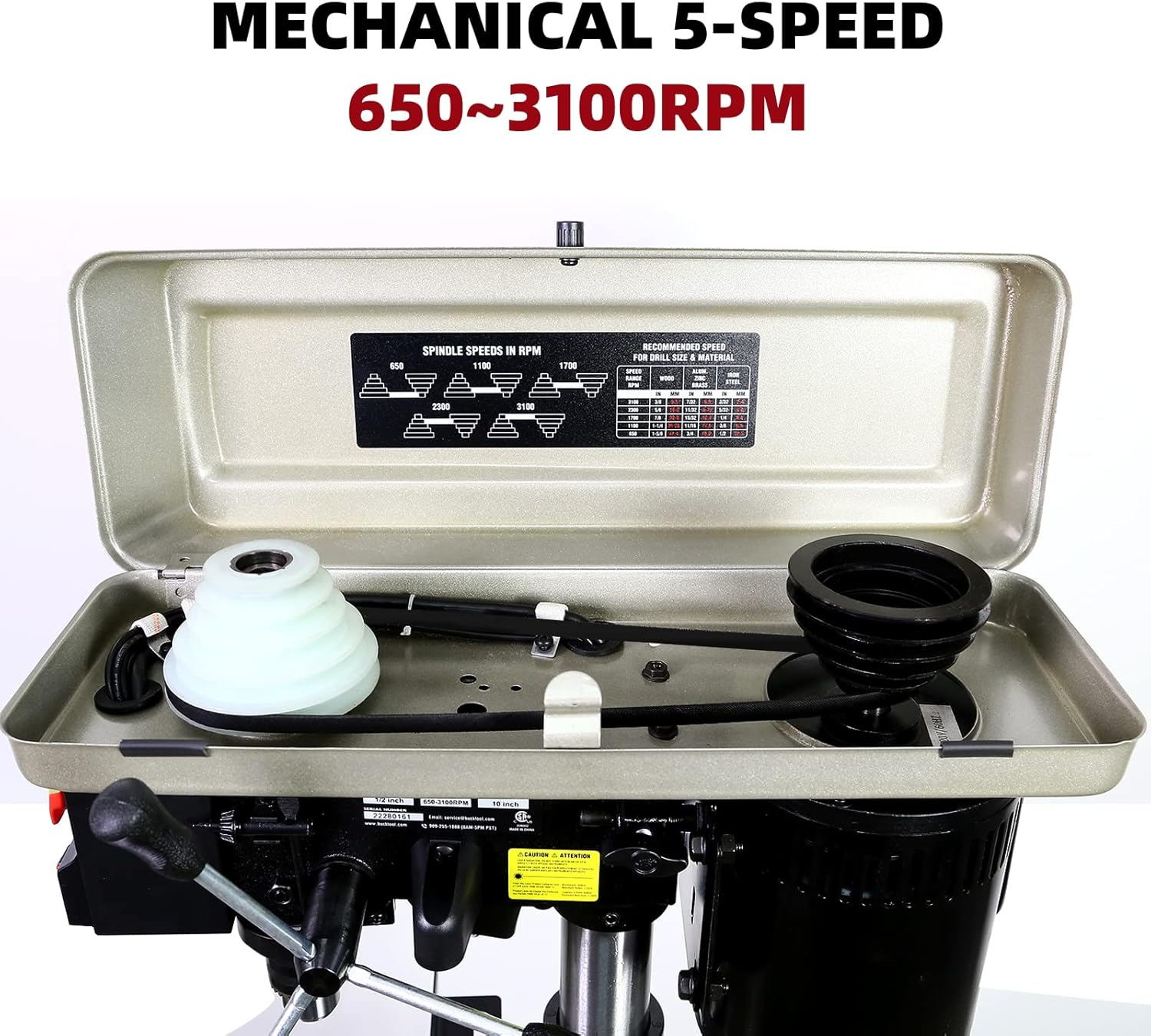
Figure 3.2: View inside the drill press head, illustrating the belt and pulley system used to adjust the spindle speed. A speed chart is typically located on the inside cover for reference.
To change speeds, open the top cover and adjust the belt position on the pulleys according to the desired RPM. Refer to the speed chart inside the cover for optimal settings for different materials (wood, plastic, metal).
3.3 Workpiece Preparation and Drilling
- Secure Workpiece: Always clamp your workpiece firmly to the drill press table using appropriate clamps. This prevents the material from spinning or shifting during drilling, ensuring safety and accuracy.
- Adjust Table: The worktable can be tilted up to 45 degrees and adjusted vertically to accommodate different workpiece sizes and angles. Use the table height adjustment handle and locking mechanism to set the desired position.
- Use Drilling Fence: The included drilling fence helps support stock on the edge and provides clearance for the chuck. Position and secure it as needed for precise alignment.
- Set Depth Stop: The drill press features a 2-inch spindle travel and an adjustable depth stop for consistent drilling depth.
- Utilize Laser and Work Light: Turn on the laser guide for accurate bit placement and the LED work light for improved visibility of your workpiece.
- Drilling: Once the workpiece is secured and settings are adjusted, slowly lower the drill bit into the material using the feed handle. Apply steady, even pressure.

Figure 3.3: The drill press table equipped with the precise drilling fence, designed to aid in accurate positioning and support of the workpiece.
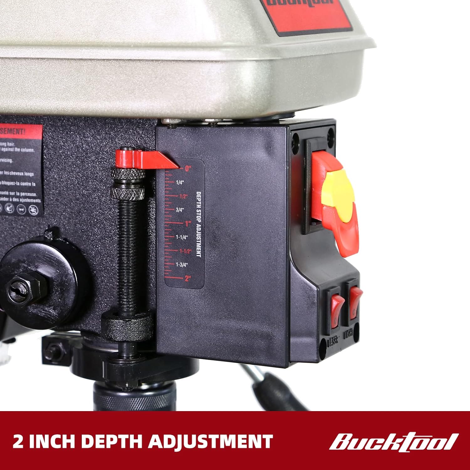
Figure 3.4: Close-up of the 2-inch depth stop adjustment mechanism, allowing for precise control over drilling depth.
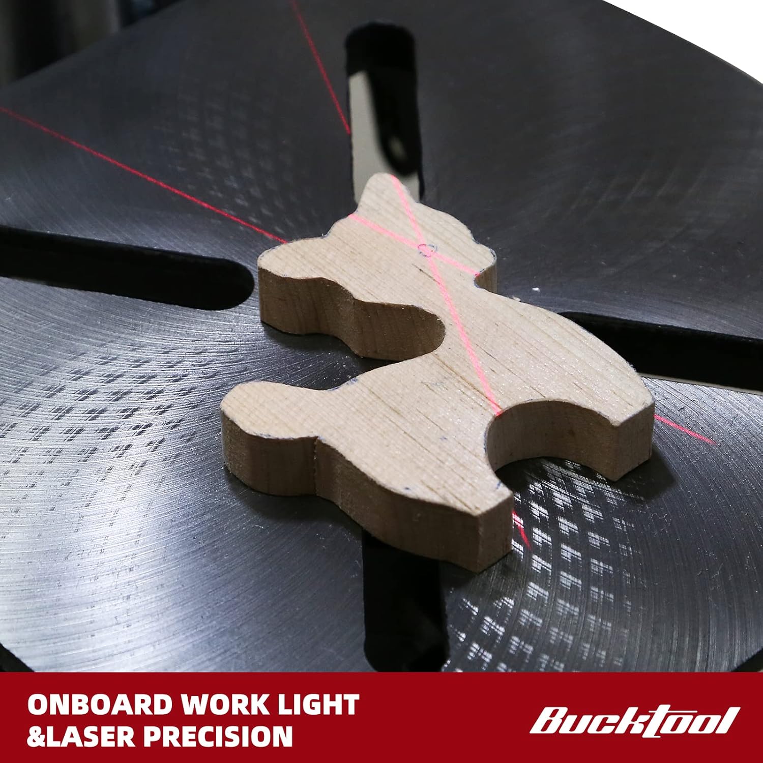
Figure 3.5: A workpiece illuminated by the onboard work light, with the laser guide projecting crosshairs for precise drilling alignment.
4. Maintenance
Regular maintenance ensures the longevity and optimal performance of your drill press.
- Cleaning: After each use, clean the drill press to remove dust, chips, and debris. Use a brush or vacuum. Do not use solvents that may damage painted surfaces or plastic parts.
- Lubrication: Periodically apply a light coat of machine oil to the column and other moving parts to prevent rust and ensure smooth operation.
- Belt Inspection: Check the drive belt for wear, cracks, or stretching. Replace if necessary. Ensure proper belt tension for efficient power transfer.
- Chuck Maintenance: Keep the chuck jaws clean and free of debris. Lubricate the chuck jaws occasionally with a light oil.
- Electrical Cord: Inspect the power cord for any damage. Do not use the drill press if the cord is frayed or damaged.
5. Troubleshooting
| Problem | Possible Cause | Solution |
|---|---|---|
| Drill press does not start. | No power, safety key not inserted, faulty switch. | Check power connection, ensure safety key is fully inserted, inspect power switch. |
| Excessive vibration during operation. | Loose components, unbalanced bit, worn belt. | Ensure all assembly bolts are tight. Check the chuck and bit for proper seating. Inspect and adjust belt tension. |
| Inconsistent drilling depth. | Depth stop not securely tightened, table movement. | Ensure the depth stop is firmly locked. Verify the table is securely clamped to the column. |
| Motor overheats. | Overloading, insufficient ventilation. | Reduce feed pressure. Ensure motor vents are clear. Allow motor to cool down. |
| Bit wobbles or runs out of true. | Bit not properly seated in chuck, damaged chuck, bent spindle. | Re-seat the bit. Inspect chuck for damage. If problem persists, contact customer support. |
6. Specifications
| Feature | Detail |
|---|---|
| Brand | Bucktool |
| Model Number | DP25016A2 |
| Power Source | Corded Electric |
| Motor | 3/4 HP, 6.0 Amp Induction Motor |
| Voltage | 120 Volts |
| Number of Speeds | 5 (650/1100/1700/2300/3100 RPM) |
| Swing | 10 inches |
| Spindle Travel | 2 inches |
| Chuck Size | 1/2 inch keyed chuck |
| Worktable Tilt | Up to 45 degrees |
| Special Features | LED Work Light, Laser Guide |
| Product Dimensions (L x W x H) | 9.45" x 18.9" x 28.74" |
| Item Weight | 54.2 pounds |
7. Warranty and Support
7.1 Warranty Information
The BUCKTOOL 10-Inch Drill Press comes with a Two-Year Limited Warranty. Please refer to the official user manual for full details regarding warranty terms and conditions.
7.2 Customer Support
For any problems or inquiries regarding your product, please contact Bucktool customer service before returning the product.
- Email: service@bucktool.com
- Website: https://www.bucktool.com
- Phone: 909-255-1088 (8AM-5PM PST)
You can also find the official User Manual in PDF format for detailed instructions and diagrams:
Related documentsDP25016A2


Ask a question about this manual
Ask about setup, troubleshooting, compatibility, parts, safety, or missing instructions. Manuals+ will review the question and use this page’s manual context to help answer it.