1. Introduction
Thank you for choosing the BTMETER Thermal Imaging Camera Gun. This device is designed for precise temperature measurement and thermal imaging, offering a wide range of applications from industrial inspections to home diagnostics. This manual provides essential information for the safe and effective use of your thermal imager.
The BTMETER Thermal Imaging Camera Gun captures temperature images and marks maximum, minimum, and center temperature points. It features a 220 x 160 IR resolution, 0.07℃ thermal sensitivity, and a temperature range of -4°F to 626°F (-20°C to 330°C). With 6GB of internal storage and adjustable emissivity, it is a versatile tool for various thermal analysis needs.

Figure 1.1: BTMETER Thermal Imaging Camera Gun and accessories.
2. Safety Information
Please read all safety warnings and instructions carefully before using this product. Failure to follow these instructions may result in electric shock, fire, or serious injury.
- Do not point the thermal imager directly at strong energy sources, such as the sun or high-power lasers, as this may damage the detector.
- Do not immerse the device in water or expose it to excessive moisture.
- Use only the specified charging cable and adapter.
- Keep the device away from extreme temperatures and corrosive environments.
- Do not attempt to disassemble or modify the device. Refer all servicing to qualified personnel.
- Ensure the lens cap is in place when not in use to protect the lens from damage.
3. Product Overview
3.1 Components and Features

Figure 3.1: Key components of the BTMETER Thermal Imaging Camera Gun.
The thermal imager features a robust design with key components for optimal performance:
- Lens Cap: Protects the infrared lens from dust and damage.
- HD Sensor (0.3 Megapixel): Captures high-quality visual data.
- Infrared Camera (220 x 160 Resolution): Detects thermal radiation and forms the thermal image.
- Trigger: Used to capture and save thermal images.
- 3.5-inch Color LED Display: Shows real-time thermal images and data.
- Navigation Buttons: For menu navigation and settings adjustment.
3.2 Key Features
- Temperature Measurement Range: -4°F ~ 626°F (-20°C ~ 330°C)
- Infrared Resolution: 220 x 160 pixels
- Thermal Sensitivity: 0.07℃
- Display: 3.5-inch large color LED
- Storage: 6GB built-in memory for image storage
- Emissivity: Adjustable from 0.01 to 1.0
- Color Palettes: Rainbow, Iron Red, White Heat, Black Heat
- Temperature Display: Max/Min/Center temperature points
- Power: USB rechargeable battery (4-6 hours standby)
4. Setup
4.1 Unboxing and Initial Inspection
Carefully remove the thermal imager and all accessories from the packaging. Inspect the device for any signs of damage. If any damage is found, do not use the device and contact customer support.
4.2 Charging the Battery
The device comes with a built-in rechargeable battery. Before first use, fully charge the battery. Connect the included Type-C USB cable to the charging port on the device and plug the other end into a standard USB power adapter (not included) or a computer USB port.

Figure 4.1: Charging the thermal imager via USB.
The charging indicator on the display will show the charging status. A full charge typically takes several hours. The device supports auto turn-off and adjustable LED display brightness to conserve battery life.
4.3 Powering On/Off
To power on the device, press and hold the power button located on the side or top of the unit until the display illuminates. To power off, press and hold the power button again until the display turns off.
5. Operating Instructions
5.1 Basic Temperature Measurement and Imaging
Point the thermal imager at the target object. The display will show a real-time thermal image. Press the trigger button to capture and save the thermal image. The device will automatically mark the maximum, minimum, and center temperature points on the captured image.
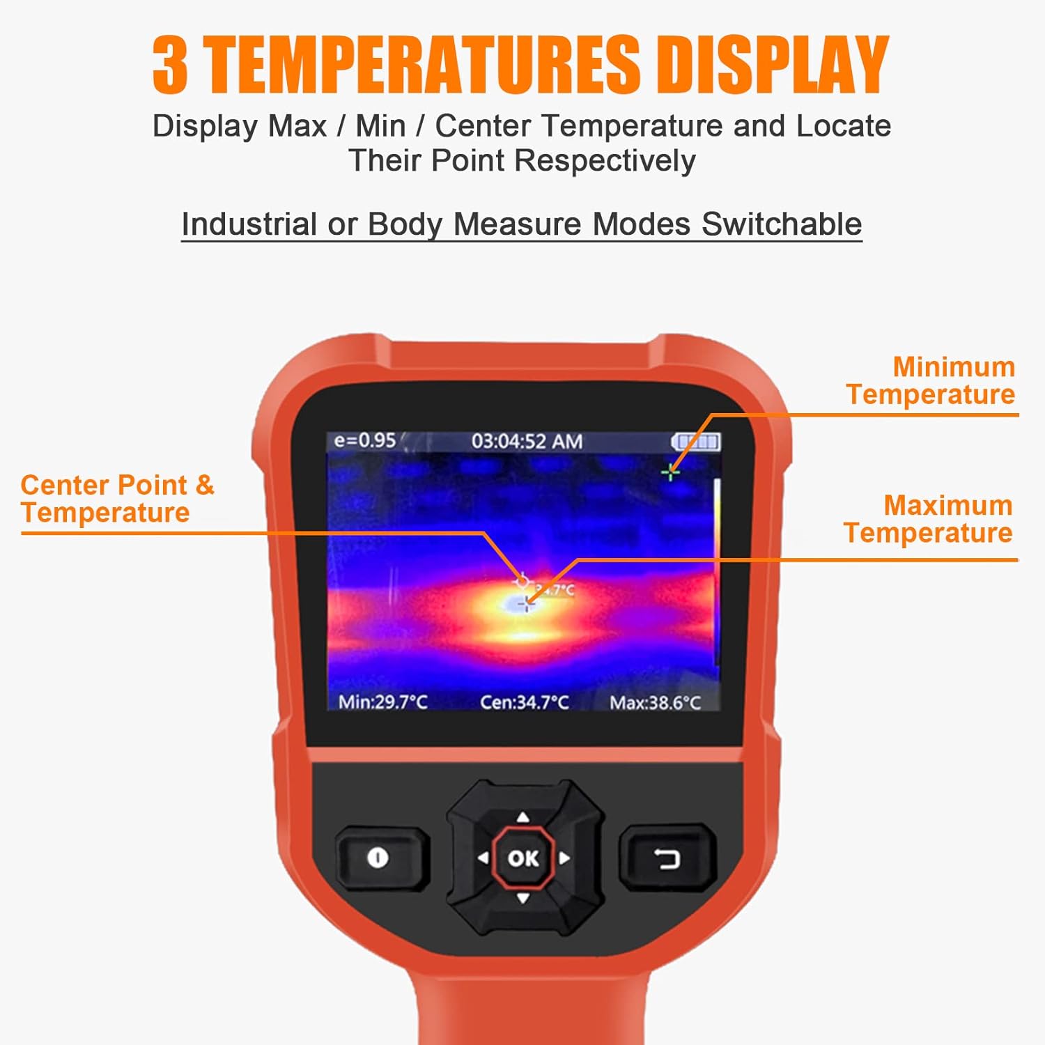
Figure 5.1: Display showing Max/Min/Center temperature points.
5.2 Adjusting Emissivity
Emissivity is a measure of an object's ability to emit infrared energy. Different materials have different emissivity values. For accurate temperature readings, adjust the emissivity setting to match the material being measured. The emissivity can be adjusted from 0.01 to 1.0 in the device settings.

Figure 5.2: Adjustable Emissivity Setting for wide applications.
5.3 Color Palettes
The thermal imager offers four color palettes to visualize temperature differences:
- Rainbow: Displays a full spectrum of colors, often used for general thermal analysis.
- Iron Red: Highlights hot spots with red and yellow tones.
- White Heat: Hotter areas appear white, cooler areas appear black.
- Black Heat: Hotter areas appear black, cooler areas appear white.
Select the palette that best suits your application and visual preference through the device's menu settings.
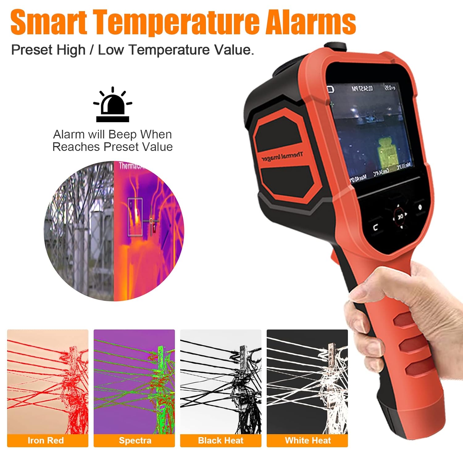
Figure 5.3: Available color palettes for thermal imaging.
5.4 Smart Temperature Alarms
The device allows you to preset high and low temperature alarm values. When the measured temperature reaches or exceeds these preset values, the device will emit an audible beep to alert the user.

Figure 5.4: Alarm settings interface.
5.5 Data Storage and Export
The thermal imager has 6GB of built-in memory to store captured thermal images. To view or export these images, connect the device to a computer using the provided USB cable. The device will appear as a removable storage device, allowing you to access and transfer the image files.

Figure 5.5: Connecting the device to a computer for data export.
6. Maintenance
6.1 Cleaning
To clean the device, wipe it with a clean, dry cloth. For stubborn dirt, a slightly damp cloth can be used, followed by a dry cloth. Do not use abrasive cleaners, solvents, or harsh chemicals, as these can damage the device's surface or lens.
6.2 Storage
When not in use, store the thermal imager in a cool, dry place, away from direct sunlight and extreme temperatures. Ensure the lens cap is securely in place to protect the infrared lens.
6.3 Battery Care
To prolong battery life, avoid fully discharging the battery frequently. If storing the device for an extended period, charge the battery to approximately 50% capacity every few months.
7. Troubleshooting
| Problem | Possible Cause | Solution |
|---|---|---|
| Device does not power on. | Battery is depleted. | Charge the device using the USB cable. |
| Thermal image is blurry or unclear. | Lens is dirty or damaged. | Clean the lens with a soft, dry cloth. Ensure the lens cap is removed. |
| Inaccurate temperature readings. | Incorrect emissivity setting. | Adjust the emissivity setting to match the material being measured. |
| Cannot connect to computer. | Faulty USB cable or port. | Try a different USB cable or a different USB port on your computer. Ensure the device is powered on. |
| Device freezes or becomes unresponsive. | Software glitch. | Perform a soft reset by holding the power button until the device turns off, then restart it. |
8. Specifications
| Parameter | Value |
|---|---|
| Model Number | HP-M2-XB-62-B |
| Temperature Range | -4°F ~ 626°F (-20°C ~ 330°C) |
| Accuracy | ±2℃ or ±2% |
| Infrared Resolution | 220 x 160 pixels |
| Thermal Sensitivity | 0.07℃ |
| Frame Rate | 9Hz |
| Field of View (FOV) | 27° x 35° |
| Display Type | 3.5-inch Digital LED |
| Emissivity | Adjustable 0.01 ~ 1.0 |
| Storage | 6GB Internal Memory |
| Connectivity | USB (Type-C) |
| Battery Life (Standby) | 4-6 hours |
| Material | Iron |
| IP Rating | IP54 |
| Shockproof | 2m drop resistance |

Figure 8.1: Detailed specifications and component overview.
9. Warranty and Support
The BTMETER Thermal Imaging Camera Gun comes with a 365-day warranty from the date of purchase. This warranty covers manufacturing defects and malfunctions under normal use.
For technical support, warranty claims, or any questions regarding the product, please contact BTMETER customer service. Lifetime technical support is provided for this product.
Please refer to the contact information provided on the product packaging or the official BTMETER website for the most up-to-date support details.


