
1. Product Overview
The Zunate ATX B75E LGA1155 Motherboard is designed to support Intel Core Pentium and Celeron LGA1155 series processors. This mainboard offers a robust platform for desktop computing, featuring low power consumption and reliable performance. It includes a DDR3 memory slot, USB 3.0 connectivity, and multiple PCIe 1X slots for graphics and other expansion cards.

Image 1.1: The Zunate ATX B75E Motherboard, showcasing its compatibility with Intel LGA1155 series processors and emphasizing its low power consumption and strong performance.
Key features include:
- CPU Support: Compatible with Intel Core Pentium and Celeron LGA1155 series processors.
- High-Speed Network: Integrated Gigabit LAN interface for fast network speeds.
- Expansion Slots: Features 8 x USB 3.0 (adaptive graphics card slots, X1 GEN1.1 speed) and 1 x DDR3 800/1333/1600MHz RAM slot.
- Video Output: Supports onboard VGA and HD multimedia interface for digital high-definition video output, providing a clear visual experience.
- Stable Power: Multi-phase power design ensures stable and accurate power delivery, distributing heat load evenly across various power chipsets to enhance CPU performance, stability, and durability.
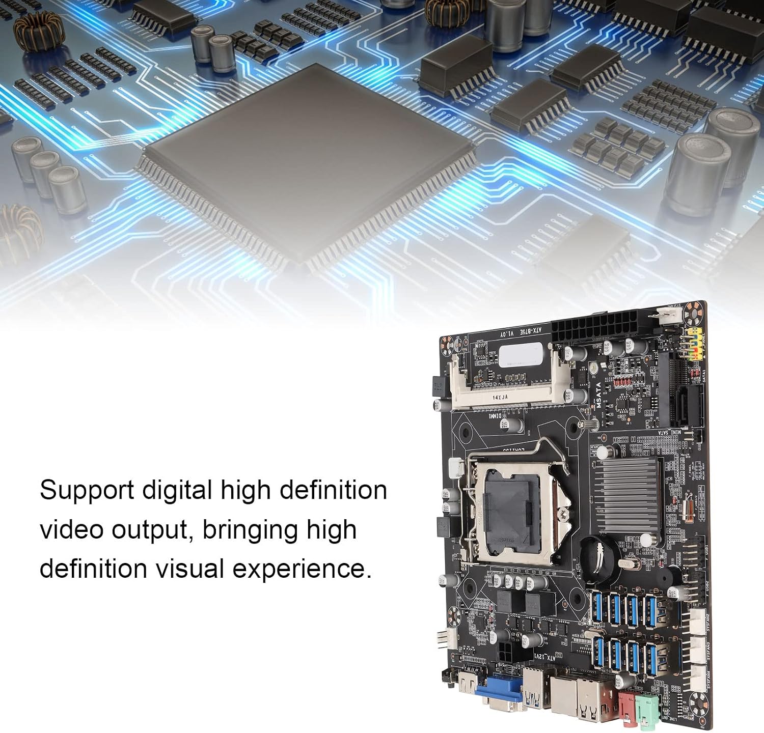
Image 1.2: The motherboard emphasizing its capability for digital high-definition video output, providing a superior visual experience.
2. Setup and Installation
Follow these steps to properly install your Zunate ATX B75E Motherboard into your computer system.
2.1 Prepare Your System
- Ensure your computer case is compatible with ATX form factor motherboards.
- Unplug the power cord from the power supply unit and discharge any static electricity by touching a grounded metal object.
2.2 CPU Installation
- Locate the LGA1155 CPU socket on the motherboard.
- Gently lift the load plate lever and open the load plate.
- Carefully align the CPU with the socket, ensuring the gold triangle on the CPU matches the triangle on the socket. Do not force the CPU into place.
- Close the load plate and secure it with the lever.
- Apply thermal paste to the CPU and install the CPU cooler according to its instructions.
2.3 RAM Installation
- Locate the DDR3 memory slot.
- Open the clips at both ends of the memory slot.
- Align the notch on the DDR3 memory module with the key in the slot.
- Press down firmly on both ends of the memory module until the clips snap into place.
2.4 Storage Device Connection
- Connect your SATA hard drives or SSDs to the SATA interface ports on the motherboard using SATA data cables.
- If using an mSATA SSD, install it into the dedicated mSATA interface slot.
- Connect power cables from your power supply to the storage devices.
2.5 Power Supply Connection
- Connect the 24-pin ATX power connector from your power supply to the main 24-pin power socket on the motherboard.
- Connect the 4-pin ATX 12V power connector from your power supply to the 4-pin CPU power socket on the motherboard.
2.6 Peripheral Connections
- Connect your monitor to the VGA or HD multimedia interface port on the motherboard's I/O panel.
- Connect USB devices (keyboard, mouse, etc.) to the available USB 3.0 ports.
- Connect your Ethernet cable to the Gigabit LAN port.
- Connect audio devices (speakers, microphone) to the MIC In and LINE Out ports.
- Connect front panel headers (power button, reset button, USB, audio) from your case to the corresponding pins on the motherboard. Refer to your case manual for specific pin assignments.

Image 2.1: A comprehensive view of the motherboard, including the CPU socket, RAM slot, SATA ports, and various connectors, along with included accessories like the I/O shield and SATA cable.

Image 2.2: A detailed view of the motherboard's rear I/O panel, highlighting the USB ports, Gigabit LAN port, VGA output, and audio jacks for external device connections.

Image 2.3: A close-up of the internal headers on the motherboard, showing connections for additional USB ports and system fans.
3. Operating Instructions
Once all components are installed and connected, you can power on your system.
3.1 Initial Boot-up
- Ensure all power cables are securely connected.
- Press the power button on your computer case.
- The system should boot up and display the BIOS/UEFI splash screen.
- If no display appears, refer to the Troubleshooting section.
3.2 BIOS/UEFI Access
To access the BIOS/UEFI setup utility, press the designated key (commonly DEL or F2) repeatedly during the initial boot-up sequence. From the BIOS/UEFI, you can configure system settings, boot order, and monitor hardware status.
3.3 Operating System Installation
After configuring the BIOS/UEFI, you can proceed with installing your preferred operating system (e.g., Windows, Linux) from a bootable USB drive or DVD.
4. Maintenance
Proper maintenance ensures the longevity and optimal performance of your motherboard.
- Dust Removal: Regularly clean dust from the motherboard and components using compressed air. Ensure the system is powered off and unplugged before cleaning.
- BIOS/UEFI Updates: Periodically check the manufacturer's website for BIOS/UEFI updates. Updates can improve stability, compatibility, and performance. Follow update instructions carefully to avoid system damage.
- Component Checks: Ensure all cables and components are securely seated. Loose connections can cause instability.
- CMOS Battery: The motherboard uses a CR2032 button cell battery (not included) for CMOS settings. If your system frequently loses time or BIOS settings, the battery may need replacement.
5. Troubleshooting
This section provides solutions to common issues you might encounter.
5.1 No Power / System Does Not Turn On
- Check if the power supply unit (PSU) is properly connected to the wall outlet and the motherboard (24-pin ATX and 4-pin ATX 12V).
- Ensure the power button cable from the case is correctly connected to the motherboard's front panel header.
- Test the PSU with another system or a PSU tester if available.
5.2 No Display on Monitor
- Verify that the monitor is powered on and the video cable is securely connected to the motherboard's VGA or HD multimedia interface port.
- Reseat the RAM module(s). Incorrectly seated RAM is a common cause of no display.
- Ensure the CPU is correctly installed and the CPU cooler is properly seated.
- If using a dedicated graphics card (via PCIe), ensure it is properly seated and powered, and connect the monitor to the graphics card's output.
5.3 System Instability / Random Crashes
- Check for overheating. Ensure CPU cooler and case fans are functioning correctly.
- Run memory diagnostic tools to check for faulty RAM.
- Ensure all drivers (chipset, graphics, etc.) are up to date.
- Check for loose power or data cables to storage devices.
5.4 Peripherals Not Detected
- Try connecting the peripheral to a different USB port.
- Ensure the peripheral's drivers are installed.
- Check BIOS/UEFI settings to ensure USB ports are enabled.
6. Specifications
Detailed technical specifications for the Zunate ATX B75E Motherboard.
| Feature | Specification |
|---|---|
| Brand | Zunate |
| Model | B75E |
| CPU Socket | LGA 1155 |
| Compatible Processors | Intel Celeron, Intel Pentium |
| Chipset | Intel B75 Express |
| RAM Memory Technology | DDR3 |
| Memory Slots | 1 x DDR3 (800/1333/1600MHz) |
| Graphics Card Interface | PCI Express |
| Video Output | Onboard VGA, HD Multimedia Interface (HDMI) |
| HDMI Ports | 1 |
| Audio Channels | MIC In, LINE Out, 5.1 Channel |
| Network | Onboard Gigabit LAN |
| SATA Interfaces | 1 x SATA, 1 x mSATA |
| Expansion Slots | 8 x USB 3.0 (adaptive graphics card slots, X1 GEN1.1 speed) |
| PSU Power Connectors | ATX 24PIN, ATX 4PIN |
| CMOS Battery | CR2032 (not included) |
7. Warranty and Support
For warranty information and technical support, please refer to the documentation provided with your purchase or contact Zunate customer service. Keep your proof of purchase for warranty claims.