1. Introduction
This manual provides detailed instructions for the installation, operation, and maintenance of the Walfront AT2-0750X Variable Frequency Drive (VFD) Inverter. This device is designed to control the speed of single-phase AC motors up to 0.75kW (1HP) by varying the frequency and voltage of the power supply. It offers high torque, precision, and a wide speed regulation range.
The AT2-0750X VFD features robust anti-tripping performance and adaptability to various environmental conditions, including power interference, temperature fluctuations, humidity, and dust. Its optimized PWM control technology and electromagnetic compatibility design contribute to low noise operation and reduced electromagnetic interference.
The inverter is designed for ease of use and wiring, utilizing convenient screw terminals for connections. It also incorporates a large heat sink for efficient heat dissipation, ensuring stable and reliable performance.
2. Safety Precautions
Failure to follow these safety instructions may result in death, severe injury, or significant property damage.
- Always ensure the power supply is disconnected before performing any wiring or maintenance on the inverter.
- Never connect the U, V, W output terminals directly to an AC power supply. Doing so will cause irreparable damage to the inverter.
- Do not install the inverter in environments containing flammable materials to prevent fire hazards.
- The ground terminal of the inverter must be properly and securely grounded.
- Avoid installing the inverter in environments with explosive gases, as this poses a risk of explosion.
- Only qualified professionals should perform wiring and internal maintenance. The inverter contains high voltage components; do not open the casing without proper authorization and safety measures.

Figure 2.1: Front view of the Walfront AT2-0750X VFD Inverter, showing the control panel and safety warning label at the bottom.
3. Product Overview and Control Panel
The Walfront AT2-0750X VFD Inverter features a user-friendly control panel for easy operation and monitoring. The panel includes a 5-digit LED display, various control buttons, and a rotary knob for speed adjustment.
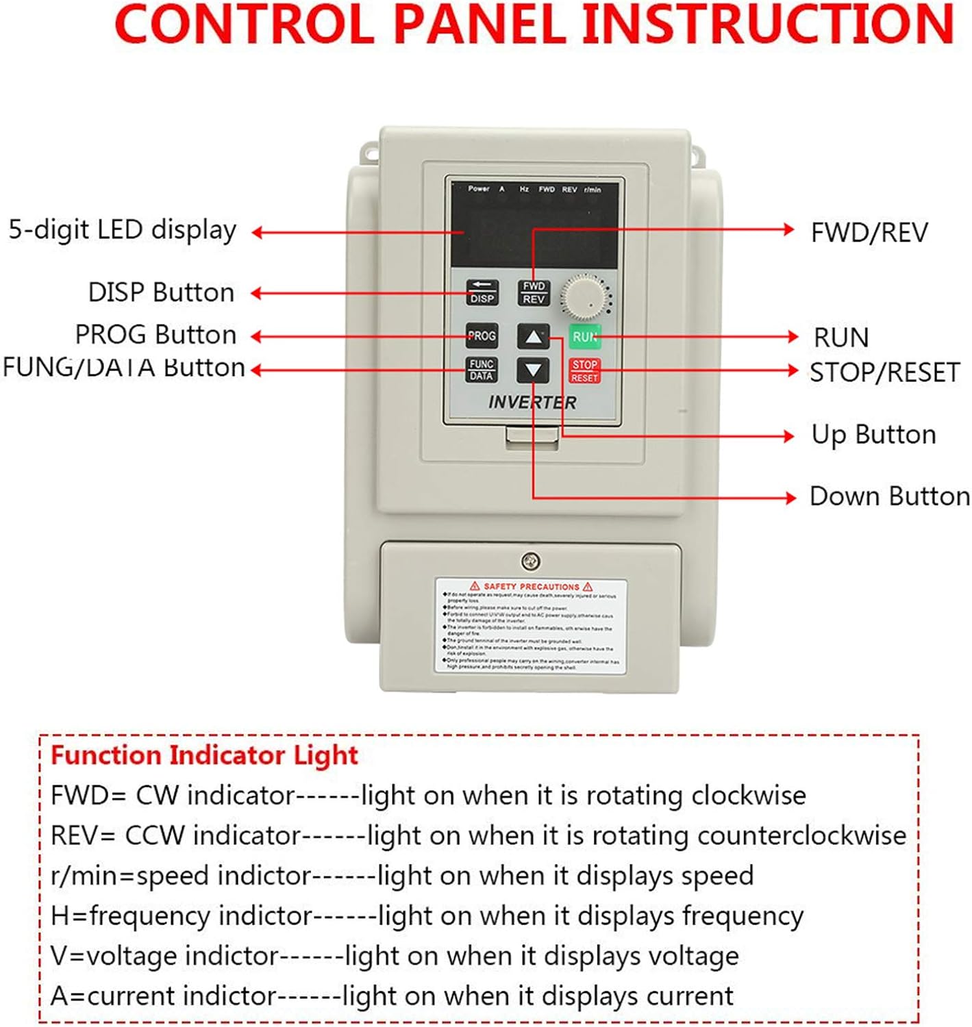
Figure 3.1: Detailed view of the control panel with labeled buttons and display.
3.1 Control Panel Components
- 5-digit LED display: Shows operational parameters such as speed, frequency, voltage, and current.
- DISP Button: Used to cycle through different display parameters.
- PROG Button: Enters or exits the parameter programming mode.
- FUNC/DATA Button: Used to select functions or confirm data entries during programming.
- FWD/REV Button: Toggles the motor's rotation direction (Forward/Reverse).
- RUN Button: Starts the motor operation.
- STOP/RESET Button: Stops the motor or resets error conditions.
- Up Button (▲): Increases parameter values or navigates menus.
- Down Button (▼): Decreases parameter values or navigates menus.
- Rotary Knob: Adjusts the motor speed (frequency).
3.2 Function Indicator Lights
The control panel includes indicator lights to show the current operational status:
- FWD (Clockwise): Lights up when the motor is rotating in the clockwise direction.
- REV (Counter-Clockwise): Lights up when the motor is rotating in the counter-clockwise direction.
- r/min (Speed): Lights up when the display shows the motor speed in revolutions per minute.
- H (Frequency): Lights up when the display shows the output frequency.
- V (Voltage): Lights up when the display shows the output voltage.
- A (Current): Lights up when the display shows the output current.
4. Setup and Installation
4.1 Wiring Diagram
Proper wiring is essential for the safe and correct operation of the VFD. Refer to the diagram below for connecting the power supply, motor, and control signals.

Figure 4.1: Wiring diagram for the Walfront AT2-0750X VFD Inverter.
- Power Supply (L, N): Connect the 220V single-phase AC power supply through a 2-phase circuit breaker to the L and N terminals.
- Ground (E): Connect the ground wire to the E terminal. Ensure a secure and effective ground connection.
- Motor Output (U, V, W): Connect the single-phase motor to the U, V, and W terminals. Ensure the motor is also properly grounded.
- External Control Inputs (X1-X6, COM): These terminals are for external control signals, such as start/stop, forward/reverse, and multi-speed commands. Refer to the detailed programming manual for specific functions.
- Analog Voltage Input (VL1/CI, 10V/5V, 15V, COM): These inputs are for external analog signals, typically used for speed reference from potentiometers or other control devices.
- Open Collector Output (SP1, COM): This output can be programmed for various functions, such as fault indication or run status.
4.2 Physical Installation
Install the VFD in a clean, dry, and well-ventilated area, away from direct sunlight, excessive heat, moisture, and corrosive gases. Ensure adequate clearance around the unit for proper airflow and heat dissipation. The VFD should be mounted vertically on a stable surface.

Figure 4.2: Side view of the VFD, showing the large heatsink designed for efficient cooling.

Figure 4.3: Close-up view of the VFD's terminal blocks for power and control wiring.
5. Operating Instructions
5.1 Basic Operation
- Power On: After ensuring all wiring is correct and secure, switch on the main power supply to the VFD. The LED display will illuminate.
- Set Speed: Use the rotary knob on the control panel to set the desired motor speed (frequency).
- Start Motor: Press the RUN button to start the motor. The FWD or REV indicator will light up depending on the direction of rotation.
- Change Direction: Press the FWD/REV button to toggle the motor's rotation direction while running or stopped.
- Stop Motor: Press the STOP/RESET button to stop the motor.
5.2 Parameter Programming
The VFD allows for advanced customization through its parameter settings. Refer to the detailed programming guide (not included in this basic manual) for a complete list of parameters and their functions.
- Enter Programming Mode: Press the PROG button. The display will show a parameter code.
- Navigate Parameters: Use the ▲ Up and ▼ Down buttons to scroll through parameter codes.
- View/Edit Parameter Value: Press the FUNC/DATA button to view the current value of the selected parameter. Use the ▲ Up and ▼ Down buttons to change the value.
- Save Changes: Press FUNC/DATA again to save the new value.
- Exit Programming Mode: Press the PROG button to exit programming mode and return to the operational display.
6. Maintenance
Regular maintenance helps ensure the longevity and reliable operation of your VFD inverter.
- Cleaning: Periodically clean the exterior of the VFD with a soft, dry cloth. Ensure ventilation openings are free from dust and debris to maintain proper airflow for cooling. Do not use liquid cleaners or solvents.
- Inspection: Regularly inspect all wiring connections for tightness and signs of wear or damage. Check for any unusual noises or odors during operation.
- Environment: Ensure the operating environment remains within the specified temperature and humidity ranges.
7. Troubleshooting
This section provides solutions to common issues you might encounter with the VFD inverter. For more complex problems, contact qualified technical support.
| Problem | Possible Cause | Solution |
|---|---|---|
| VFD does not power on | No input power; Blown fuse/breaker; Incorrect wiring. | Check power supply; Inspect circuit breaker/fuse; Verify L and N connections. |
| Motor does not run | RUN button not pressed; Incorrect motor wiring (U, V, W); Fault condition; Parameter settings. | Press RUN; Check motor connections; Clear any fault codes; Review basic operating parameters. |
| Motor runs in wrong direction | FWD/REV setting; Motor phase sequence. | Press FWD/REV button; If still incorrect, swap any two motor output wires (U, V, W). |
| Overcurrent/Overload fault | Motor overloaded; Short circuit in motor or wiring; Acceleration time too short. | Reduce motor load; Check motor and wiring for shorts; Increase acceleration time parameter. |
| Overvoltage/Undervoltage fault | Unstable input voltage; Deceleration time too short (overvoltage). | Check input power supply stability; Increase deceleration time parameter. |
8. Specifications
Below are the technical specifications for the Walfront AT2-0750X VFD Inverter.
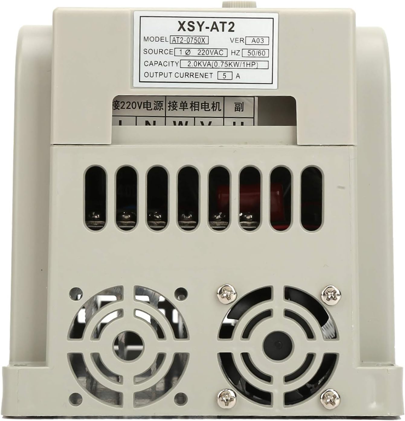
Figure 8.1: Rear view of the VFD, showing the model and electrical specifications label.
| Feature | Specification |
|---|---|
| Brand | Walfront |
| Model Number | AT2-0750X |
| Input Voltage | 220V AC (Single-Phase) |
| Input Frequency | 50/60 Hz |
| Output Voltage | 220V AC (Three-Phase, for single-phase motor control) |
| Rated Power Capacity | 0.75kW (1HP) |
| Output Current | 5 A |
| Efficiency | 90% |
| Material | Plastic + Aluminum |
| Product Dimensions (L x W x H) | 13 x 13 x 13 cm |
| Item Weight | 1.2 Kilograms |
| Certification | CE |
| Country of Origin | China |
9. Warranty and Support
Information regarding specific warranty terms and customer support contacts is not available in the provided product data. Please refer to the product packaging or the seller's website for warranty details and support options.


