1. Product Overview
The Watts LF007M2-QT 1 1/2" Lead Free Double Check Valve Assembly is engineered to prevent the backflow of polluted water from entering the potable water supply. This is crucial for protecting against back siphonage and backpressure, adhering to national plumbing codes and water authority requirements. Its design emphasizes ease of maintenance with a compact, modular structure and a single access cover for in-line repairs. It is ideally suited for continuous pressure piping applications and cross-connections identified as non-health hazards, as well as for controlling contaminants at the service line entrance.

Image: Watts LF007M2-QT Double Check Valve Assembly, showing the main body, shutoff valves, and test cocks.
Product Overview Video (Similar Product Type)
Video: An animated overview of a Bronze Double Check Valve Backflow Preventer Assembly, highlighting its features and typical installation in a residential setting. This video provides a general understanding of double check valve assemblies.
Product Overview Video (Related Series)
Video: An overview of the Watts Series LF825Y Reduced Pressure Zone Assembly. While a different model, it demonstrates the general principles and applications of Watts backflow prevention devices.
2. Features
- Lead-Free Bronze Construction: Ensures durability and compliance with lead-free regulations.
- Replaceable Check Seats and Discs: Allows for economical repairs and extended product life.
- Modular Compact Design: Facilitates easy installation and maintenance without requiring special tools.
- One Cover Design: Simplifies maintenance procedures.
- Top-Mounted Test Cocks: Provides convenient access for testing and servicing.

Image: A side view of the Watts LF007M2-QT Double Check Valve Assembly, highlighting the quarter-turn shutoff valves and compact design.
3. Specifications
| Material | Bronze |
| Item Dimensions (L x W x H) | 17.88 x 9.5 x 7.25 inches |
| Inlet Connection Size | 1.5 Inches |
| Inlet Connection Type | National Pipe Tapered (NPT) |
| Outlet Connection Size | 1.5 Inches |
| Outlet Connection Type | NPT |
| Number of Ports | 2 |
| Specification Met | ASSE 1013, NSF/ANSI 372, RoHS, EPA |
| Item Weight | 6.72 pounds |
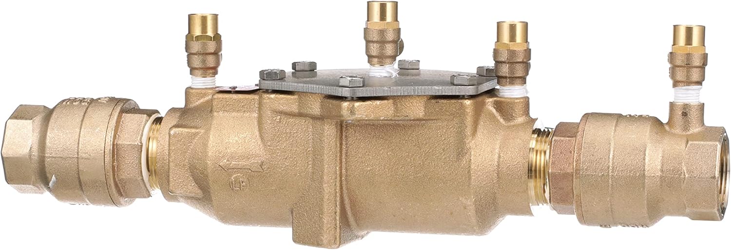
Image: A comprehensive view of the Watts LF007M2-QT Double Check Valve Assembly, showcasing its full dimensions and components.
4. Installation and Setup
Always consult local building and plumbing codes prior to installation. If this information is not consistent with local building codes, the local codes should be followed. It is important that the assembly be easily accessible to facilitate testing and servicing. A properly-sized drain line and air gap should be piped from the relief valve connection of the assembly. In areas where freezing conditions occur, backflow preventers should be installed above ground in an insulated enclosure. Backflow preventers should not be installed in pits unless approved by local codes. In such cases, a modified pit installation is preferred.

Image: A side view of the Watts LF007M2-QT Double Check Valve Assembly, illustrating its connection points for installation.
5. Operating Instructions
The Watts LF007M2-QT Double Check Valve Assembly is designed for continuous pressure piping applications. Once properly installed and tested, the device operates automatically to prevent backflow. Regular testing by a certified backflow prevention device tester is required to ensure proper operation and compliance with local regulations.

Image: A top view of the Watts LF007M2-QT Double Check Valve Assembly, showing the access cover and test cocks.
6. Maintenance and Troubleshooting
This section addresses the inspection and repair of backflow prevention assemblies. Before beginning any work, please familiarize yourself with these procedures to avoid harming yourself or damaging the valve. These instructions, as well as specification sheets, repair kit ordering information, and additional product resources can be found online at watts.com.
Common Issues and Initial Checks
Two common issues you may encounter are an assembly that spits water from the relief valve vent periodically, or an assembly that drips continually from the relief valve vent. No special tools are required for initial troubleshooting; only a standard screwdriver is needed.
- Continuous Dripping from Relief Valve:
- Close shut-off valve number 2.
- If the drip stops, it indicates a fouled second check with a backpressure condition.
- If the drip does not stop, open test cock number 4 to create a downstream flow.
- If the discharge of water from the relief valve vent becomes less or stops, it most likely indicates a fouled first check.
- If the discharge of water from the relief valve vent does not stop with shut-off valve number 2 closed and test cock number 4 opened completely, it's most likely the relief valve. On occasion, it may be both a fouled first check and a relief valve issue.
Servicing the Assembly
To service the assembly, follow these steps:
- Close shut-off valve number 1.
- Close shut-off valve number 2 (it may already be closed if you just performed troubleshooting).
- Relieve pressure by opening test cock number 2, test cock number 3, and test cock number 4.
- Once all pressure is relieved, remove the valve cover bolts.
- Lift the cover straight off. The relief valve stem and diaphragm assembly will normally remain with the cover.
- Remove the relief valve spring (it will be free inside the body).
- Remove the retainer.
- Remove check valve number 2 and check valve number 1.
- Remove the relief valve seat.
Inspection and Reassembly
- Inspect the seat for any imperfections on its surface. Replace if necessary.
- On the disc assembly, check the rubber for any imperfections, tears, rips, or buried debris. Clean or replace as necessary. Use a small screwdriver to remove the silicone disc from the holder for inspection.
- Before reassembling, inspect the spring cage to ensure it's in good shape and that the disc holder moves freely.
- Reassemble the components. Note that the check seats are attached to the cage with a bayonet-type locking arrangement. Hold the cage in one hand, push the seat inward against the cage, and rotate 1/8 of a turn clockwise (for 1/4" to 2" valves) or counterclockwise (for 2 1/2" and 3" valves) to release/secure components.
- Before installing check assemblies, apply an FDA-approved lubricant sparingly to the O-rings.
- Reinstall check valve number 1 and check valve number 2. Note that the seats and springs of the two checks are not interchangeable; ensure they are returned to their correct locations for proper function.
- Reinstall the retainer.
- Reinstall the spring.
- Reinstall the relief valve with the cover. Press down on the cover and reinstall the cover bolts.
- Once reassembly is complete, refer to the installation start-up procedure to return the valve assembly to service.
Troubleshooting and Service Video (Related Series)
Video: This video demonstrates troubleshooting and service procedures for the Watts LF009 Reduced Pressure Zone Assembly. While the model differs, the general steps for identifying and resolving common issues like relief valve spitting or dripping, and the process for disassembling, inspecting, and reassembling internal components, are applicable to many Watts backflow preventers, including double check valve assemblies.
7. Warranty Information
For detailed warranty information, please refer to the official Watts product warranty documentation included with your purchase or visit the Watts website. General warranty terms typically cover manufacturing defects under normal use and service conditions.
8. Customer Support
For technical assistance, replacement parts, or further inquiries, please contact Watts customer support. You can find contact information on the official Watts website or in the documentation provided with your product.
Watts Website: www.watts.com


